Searching For Low-Phase-Noise Synthesizers
This file type includes high resolution graphics and schematics when applicable.
Clean, quiet frequency synthesizers are essential for modern communications systems. But the performance of RF/microwave frequency synthesizers is often tied to a lower-frequency reference oscillator, such as an oven-controlled crystal oscillator (OCXO), and great effort is often required to produce a microwave frequency synthesizer with low phase noise. To demonstrate, a 10.24-GHz frequency synthesizer with OCXO reference source was developed, and the design path to that synthesizer will be traced.
Phase noise is a vital parameter for oscillators and synthesizers in communications and other systems. It is measured as the ratio between the power density in one phase noise modulation sideband, per hertz, and total signal power.1 Typically, a wideband synthesizer will exhibit more noise than a single-frequency synthesizer. When low noise is required, a single-frequency synthesizer can be combined with frequency mixers to build a wideband synthesizer with low noise.
The phase noise of the signal produced by the synthesizer is determined by the performance of the oscillator used to build the synthesizer, the performance of the reference, and the transfer characteristic and intrinsic noise of the synchronization method. Major contributors to phase noise are the internal oscillator and the reference source (for noise offset far from and close to the carrier, respectively). An OCXO may be used as the reference for low-noise applications, possibly locked to a rubidium clock or a 1 pulse-per-second GPS source.
The phase noise performance of the oscillators has a fundamental limit imposed by the Johnson-Nyquist theory. A resistor at room temperature (300 K) produces about -173.82 dBm/Hz noise, with this power level equally split in two sidebands. A signal with 0-dBm power will have a lower phase-noise limit of -177 dBc/Hz, improving upon -177 dBc/Hz only if the signal carries more than 0-dBm power, as with some low-noise OXCOs.2,3 The best low-noise oscillators are capable of approaching this limit at far offset frequencies. For close-in frequency offsets the phase noise will be determined by the quality factor (Q) of the resonator.
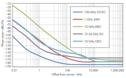
The frequency offset at which the phase noise approaches the theoretical limit is roughly proportional to the frequency of the oscillator, increasing as the frequency increases. Figure 1 shows typical performance levels for different low-noise oscillators, including a 100-MHz OCXO, a 1-GHz surface-acoustic-wave (SAW) oscillator, a 10-GHz dielectric-resonator oscillator (DRO), a 10.24-GHz sapphire oscillator (SO), and a 10-GHz opto-electronic oscillator (OEO).4-10
In Fig. 1, the OCXO phase noise exceeds the -177 dBc limit, because its power is 13 dB higher than the 0-dBm limit. The lowest-frequency oscillators typically exhibit the lowest noise floors. They also show lower close-in phase noise, since the quality factor (Q) of lower-frequency resonators is higher, and because the flicker characteristics associated with these resonators is better. When using these oscillators as the reference of a synthesizer, their noise contribution is scaled by 20log(Fout/Fref). Thus, the noise contribution of a 100-MHz OCXO will be increased by 40 dB when producing a 10-GHz signal. Figure 2 shows the expected noise from these oscillators when used to generate a 10-GHz signal.
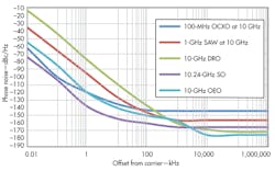
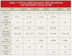
As that figure indicates, the lowest close-in phase noise is from the sapphire oscillator (SO), followed closely by the OCXO. The lowest phase noise far from the carrier is for the optoelectronic oscillator (OEO) and the dielectric-resonator oscillator (DRO). Combining the SO or OCXO with the OEO or DRO could achieve lower noise levels. Additional specifications are available in Table 1.
This file type includes high resolution graphics and schematics when applicable.
Building Blocks
This file type includes high resolution graphics and schematics when applicable.
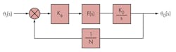
Figure 3 shows a typical second-order PLL circuit that can be used as the starting point for building a frequency synthesizer. It uses a phase detector, loop filter, oscillator, and feedback divider.10-12 Parameter Kφ is the gain of the phase detector, F(s) is the transfer characteristic of the loop filter, K0 is the VCO sensitivity, and N is the feedback divider ratio. Considering the PLL a control system, the closed-loop transfer function (transfer function of the input phase noise to the output signal) can be described by Eq. 1:
B(s) = φ0(s)/φi(s) = N[(2ξωns + ω2n)/(s2 + 2ξωns + ω2n)] (1)
with F(s), the natural pulsation (ωn), and the damping factor of the control system (ξ) described by Eqs. 2, 3, and 4, respectively:
F(s) = (1 + τ2s)/(τ1s) (2)
ωn = [KφK0/(Nτ2)]0.5 (3)
ξ = ωnτ2/2 (4)
By analyzing Eq. 1, as the input phase-noise frequency offset decreases towards zero, the transfer function approaches N. Essentially, the input phase noise is amplified by the feedback divider ratio, increasing by a factor of 20logN (in dBc). The unity gain frequency (f0) is independent on the damping factor and is given by Eq. 513:
f0 = [(2)0.5/2π]ρn (5)
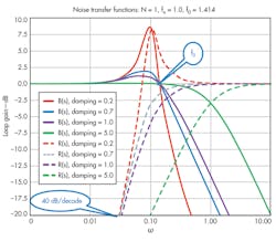
The VCO noise transfers to the output of the PLL by a second-order highpass relationship given by Eq. 6:
R(s) = s2/(s2 + 2ξωns + ω2n (6)
For low offset frequencies, the VCO noise is attenuated with a 40-dB/decade slope, while for far offset frequencies, the VCO noise passing to the output is unaffected by the loop.
The magnitudes of the B(s) and K(s) noise transfer functions are plotted in Fig. 4. For a damping factor of 0.707, shown by the blue trace on Fig. 4, the peaking has a value of 2.09 dB. If the PLL is underdamped (ξ < 0.707), peaking can be large, making the system unstable. Peaking can be reduced by increasing the damping factor, but this takes the B(s) and R(s) trace decrease less sharply beyond the natural frequency.
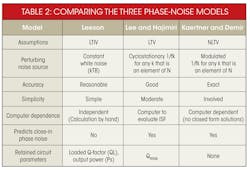
Noise models can be categorized as linear time invariant (LTIV), linear time variant (LTV), and nonlinear time variant (NLTV) models, in order of increasing complexity. Leeson’s model15 is based on LTIV oscillator properties, such as resonator Q, feedback gain, output power, and noise figure. Additional models include an LTV model16 and an NLTV configuration using a perturbation model based on numerical techniques.17-20
Phase noise has been analyzed by means of a number of different models, with both time- and frequency-domain techniques applied.21-26 (The relative strengths and weaknesses of the three phase-noise models are compared in Table 2, included in the online version of this article). When comparing noise models for harmonic (LC-resonator-type) and nonharmonic oscillator circuits (RC-oscillator-type) oscillator circuits, a designer must choose the noise model since none of the models provide closed-form solutions for phase noise.
This file type includes high resolution graphics and schematics when applicable.
Lowering Noise
This file type includes high resolution graphics and schematics when applicable.
In typical implementations, a synthesizer would use a feedback divider to control the frequency produced by the oscillator. The feedback divider’s output noise exhibits the same lowpass transfer characteristics [B(s)] as the input noise, with the divider’s close-in noise of greater importance than its noise level. Such a divider is built with logic gates, using typical technologies as TTL, CMOS/BiCMOS, and ECL, but rarely as a regenerative divider based on frequency mixers. TTL dividers can achieve low noise levels28, to -170 dBc/Hz, with good close-in noise, but their maximum clock frequency rarely exceeds 150 MHz.
Reducing the reference frequency from 100 MHz to 10 MHz would result in degradation of output phase noise of 20 dB, making the TTL divider unsuitable for locking with 100-MHz signals. CMOS/BiCMOS dividers can achieve similar noise levels at offsets greater than 10 MHz, but with more flicker in higher close-in noise levels that makes them poor choices for low-noise synthesizers. A better choice would be using ECL dividers, which typically exhibit noise levels of -155 dBc/Hz.
Direct frequency synthesis can achieve lower noise than when using feedback dividers and phase-detector combinations. Direct synthesis employs harmonic multipliers, based on step-recovery, PIN, or Schottky diodes, to generate higher-frequency signals. Such diodes allow multiplication of the 100-MHz signal from an OCXO with minimal degradation in noise, with an equivalent noise floor of about -174 dBc/Hz. The synthesis approach can achieve a slightly better noise performance when using references having power levels considerably higher than 0 dBm. The drawback of this method is the high far-offset output noise, with 20logN degradation.
Improved noise performance can be achieved by combining the direct frequency synthesis approach with a PLL method. A high-frequency phase detector is used to lock the oscillator to the harmonic of the reference clock produced by diode harmonic multipliers. By using a low-noise OCXO with a low-noise high-frequency oscillator, such as a DRO or SAW oscillator, this hybrid method is capable of achieving excellent noise levels. Close-in performance is determined by the OCXO and harmonic multiplier, while far-offset performance is determined by the high-frequency oscillator.
The KFSULN1024-100 DRO reference synthesizer is an implementation of such an approach, providing a 10.24-GHz output signal with low noise. The design locks a 10.24-GHz DRO from Synergy Microwave Corp. to the harmonics of an internal OCXO reference, using a low-noise PLL with double-balanced mixer serving as phase detector. By using frequency multiplication from the reference, the noise performance required from the mixer and loop filter is relaxed by about 40 dB. The design employs low-noise operational amplifiers to achieve low noise levels.
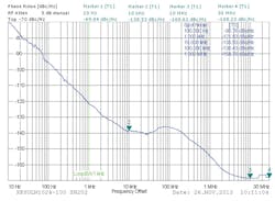
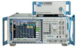
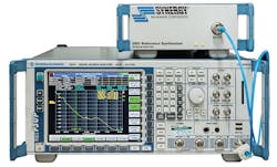
The synthesizer was characterized with a model FSUP signal source analyzer from Rohde & Schwarz. The synthesizer and test system were both placed inside a Faraday cage to minimize the effects of outside noise sources. Figure 5 shows the test system, while Fig. 6 shows the test results.
The synthesizer produces a +10 dBm signal at 10.24 GHz. The low-noise internal OCXO determines the synthesizer’s performance for offset frequencies between 10 Hz and 1 kHz, with -70 dBc/Hz phase noise at 10 Hz offset and -121 dBc/Hz at 1 kHz offset. Low-noise synthesis techniques produce a low noise floor of -138 dBc at 10 kHz offset. Above 1 MHz, the noise floor is determined by the DRO and reaches -168 dBc/Hz.
Prof.-Dr.-Ing.-habil Ulrich Rohde, Chairman*
Dr. Ing. Ajay Kumar Poddar, Chief Scientist
Dorin Calbaza, Senior Design Engineer
Synergy Microwave Corp., 201 McLean Blvd., Paterson, NY 07504; (973) 881-8800, FAX: (973) 881-8361.
*Ulrich Rohde is also affiliated with Cottbus University, Brandenburg, Germany.
This file type includes high resolution graphics and schematics when applicable.
References
This file type includes high resolution graphics and schematics when applicable.
1. IEEE STD 1139-2008, IEEE Standard Definitions of Physical Quantities for Fundamental Frequency and Time Metrology-Random Instabilities,” February 2008, Digital Object Identifier: 10.1109/IEEESTD.2008.4797525, pp. c1-35.
2. U.L. Rohde and A.K. Poddar, “Technique to Minimize Phase noise of Crystal Oscillators,” Microwave Journal, May 2013, pp. 132-150.
4. U.L. Rohde and A.K. Poddar, “ Latest Technology, Technological Challenges, and Market Trends for Frequency Generating and Timing Devices,” IEEE Microwave Magazine, October 2012, pp.120-134.
5. U.L. Rohde and A.K. Poddar, “DRO Drops phase-noise levels,” Microwaves & RF, February 2013, pp. 80-84.
6. Ulrich Rohde, Ajay Poddar, and Anisha Apte, “Getting Its Measure,” IEEE Microwave Magazine, Vol. 14, No. 6, pp. 73-86.
7. Ulrich Rohde, Ajay Poddar, and Anisha Apte, “How Low Can They Go, Oscillator Phase Noise Model, Theoretical, Experimental Validation, and Phase Noise Measurements,” IEEE Microwave Magazine, Vol. 14, No. 6, pp. 50-72.
8. Li Zhang, A.K. Poddar, U.L. Rohde, and A.S. Daryoush, “Analytical and Experimental Evaluation of SSB Phase Noise Reduction in Self-Injection Locked Oscillators Using Optical Delay Loops,” IEEE Photonics Journal, Vol. 5, No. 6, pp. 1-18.
9. A.K. Poddar, “Slow Wave Resonator Based Tunable Multi-Band Multi-Mode Injection-Locked Oscillators” Dr.-Inh.-habil Thesis, BTU Cottbus, Germany (draft thesis submitted for defense on March 2013).
10. U.L. Rohde, Microwave Wireless Synthesizers: Theory and Design, Wiley, New York, 1997, p. 25.
11. U.L. Rohde and A.K. Poddar, “A Digital Frequency Synthesizer Using Adaptive Mode-Coupled Resonator Mechanism for Low Noise and Low Jitter Applications,” IEEE International Symposium on Circuits and Systems (ISCAS), 2011.
12. U.L. Rohde and A.K. Poddar, “VCSO Technology Silences Synthesizers,” Microwaves & RF, February 2011.
13. J.A. Crawford, “Advanced Phase-Locked Techniques,” Artech, Norwood, MA, p. 28.
14. Behzad Razavi, RF Microelectronics, Prentice-Hall, Englewood Cliffs, NJ, 2011, p. 613.
15. D.B. Leeson, “A Simple Model of Feedback Oscillator Noise Spectrum,” IEEE Proceedings, 1966, pp. 329-332.
16. T.H. Lee and A. Hajimiri, “Oscillator Phase Noise: A Tutorial,” IEEE Journal of Solid-State Circuits, Vol. 35, No. 3, March 2000, pp. 326-336.
17. A. Demir, A. Mehrotra, and J. Roychowdhury, “Phase noise in oscillators: a unifying theory and numerical methods for characterization,” IEEE Transactions on Circuits & Systems I, Vol. 47, No. 5, May 2000, pp. 655-674.
18. M. Nick, “New Q-Enhanced Planar Resonators for Low Phase-Noise Radio Frequency Oscillators,” Ph.D. Dissertation, Electrical Engineering, University of Michigan, 2011.
19. F.X. Kaertner, “Analysis of White and üb Noise in Oscillators,” International Journal of Circuit Theory and Application, Vol. 18, 1990, pp. 485-519.
20. A. Demir, “Phase Noise and Timing Jitter in Oscillators with Colored-Noise Sources,” IEEE Transactions on Circuits and Systems 1, Vol. 49, No. 12, December 2002, pp. 1782-1791.
21. J.C. Nallatamby, M. Prigent, M. Camiade, and J. Obregon, “Phase noise in oscillators – Leeson formula revisited,” IEEE Transactions on Microwave Theory and Techniques, Vol. 51, No. 4, April 2003, pp. 1386-1394.
22. A. Suárez, S. Sancho, S. Ver Hoeye, and J. Portilla, “Analytical comparison between time- and frequency-domain techniques for phase-noise analysis,” IEEE Transactions on Microwave Theory and Techniques, Vol. 50, No. 10, October 2002, pp. 2353-2361.
23. S. Ver Hoeye, A. Suárez, and J. Portilla, “Techniques for oscillator nonlinear optimization and phase-noise analysis using commercial Harmonic-Balance software,” 2000 IEEE MTT-S Digest, pp. 95-98.
24. V. Rizzoli, F. Mastri, and D. Masotti, “General noise analysis of nonlinear microwave circuits by the piecewise Harmonic Balance technique,” IEEE Transactions on Microwave Theory and Techniques, Vol. 42, No. 5, May 1994, pp. 807-819.
25. A. Abidi, “How phase noise appears in oscillators.”
26. U.L. Rohde and D.P. Newkirk, “RF/Microwave Circuit Design for Wireless Applications,” Wiley-Interscience, New York, 2000, p. 644.
27. Ulrich L. Rohde, Digital PLL Frequency Synthesizers - Theory and Design, Prentice-Hall, Englewood Cliffs, NJ, 1983.
28. Ulrich L. Rohde, “A New and Efficient Method of Designing Low Noise Microwave Oscillators,” Dr.-Ing. Thesis, BTU Cottbus, Germany, 2004.
This file type includes high resolution graphics and schematics when applicable.
About the Author
Ulrich L. Rohde
Chairman of Synergy Microwave Corp
Ulrich L. Rohde is Chairman of Synergy Microwave Corp., Paterson, NJ and President of Communications Consulting Corp. Rohde studied electrical engineering and radio communications at the universities of Munich and Darmstadt, Germany. He holds a PhD in electrical engineering (1978) and an Sc.D. (hon., 1979) in radio communications. In 2004, he obtained a Dr.-Ing. Degree from the University in Berlin, Germany. In 2011, Rohde earned the Prof. Dr.-Ing. habil. degree from the University of Cottbus, Germany. Rohde has published more than 200 scientific papers and either contributed to or written a large number of books.
