Meet The Challenges Of Testing Eight-Antenna LTE

Various multiple-input multiple-output (MIMO) antenna techniques are being used by TD-LTE, FDD-LTE, and LTE-Advanced (LTE-A) wireless technologies. Given the growing complexity in MIMO systems, related test methodologies will also become more challenging. For example, currently deployed MIMO technologies implement two antennas to improve channel performance. Yet some LTE communities are pioneering eight-antenna technologies to reap even higher performance gains. Such advanced technologies will make the choice of test methodology even more critical.
To find the right approach, it is essential to have a solid understanding of the antenna techniques used for each version of LTE. For example, beamforming is a key feature of TD-LTE. While it is an attractive transmission scheme for some scenarios (e.g., open rural area or hotspot coverage), however, it is not always the optimum approach. Beamforming boosts the received signal-to-noise ratio (SNR) of a cell for enhanced coverage or to improve the user experience near the cell edge. It also spatially confines the signal to minimize interference. In areas where the SNR is sufficient, though, beamforming does not result in increased data rates.
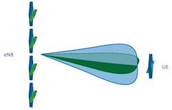
By spatially multiplexing simultaneous data streams, MIMO can increase data throughput under low-correlation, high-SNR channel conditions. To optimize MIMO data rates, TD-LTE employs eight antenna elements. In Figure 1, four antennas (shown as blue) are physically polarized at the same angle while the other four (shown as green) are physically orthogonal to the first four.

Each set of four antenna elements can boost SNR by forming a beam which is directed toward specific user equipment (UE). The two orthogonally polarized beams effectively resemble two low-correlation antennas—even though the actual spatial correlation may be high. As a result, this antenna configuration enlarges the coverage area in which high-data-rate transmission is possible (Fig. 2).
In addition to TD-LTE, eight-antenna techniques can be used in FDD-LTE. Network operators may use this antenna configuration to enhance uplink reception by offsetting the link budget limitations of low-power UEs. The 3GPP’s RAN1 working group is actively discussing the practical deployment of eight-antenna techniques in LTE-A.1,2
In traditional performance testing, antenna patterns—or signal gains in each direction of an antenna array—are usually disregarded. This is partially due to an assumption—based on legacy testing in single-input, single-output (SISO) systems—that antennas are omnidirectional. But this is not true for most base stations. The directional aspects of signal strength play a big role in MIMO spatial channels and an even more significant role in beamforming applications. Considering antenna patterns is therefore important when testing eight-antenna systems.
To fully exploit the benefits of eight-antenna arrays, LTE and LTE-A systems use advanced transmission schemes like dual-layer beamforming and receiver techniques like Interference Rejection and Combining (IRC). IRC is a technique in which an eNodeB base transceiver station (BTS) uses information gathered from various UEs (typically cross-co-variance between noise sources) to intelligently reject noise. Such schemes add to the complexity of emulating the MIMO channel. In addition, they present the following testing challenges:
Number of channels:To test a beamforming system, one must set up the MIMO channel. In TD-LTE, the downlink and uplink radio links are characteristically identical. In FD-LTE, the channels may or may not be correlated to some degree—depending on such factors as frequency separation or the level of fading being observed (i.e., Rayleigh fading, shadow fading, etc.). Any RF channels created in the lab for test purposes must account for each of these details.
For eight-antenna systems, such testing obviously involves a large number of RF channels. An 8x2 bidirectional MIMO channel, for example, requires 16 RF channels. In many labs, space is a factor. Thus, delivering this significant increase in capabilities without a proportional increase in test-stand size requires consideration.
In addition, channel reciprocity requires that an 8x2 bidirectional MIMO testing system is phase-calibrated for testing a system’s beamforming capabilities. Effective phase calibration and alignment of the channels are critical factors for reliable and efficient testing. This increase in the number of channels also requires dense integration of RF hardware into the system. Otherwise, it can be next to impossible to accurately and reliably cable RF channels with outboard splitters, combiners, circulators, etc.
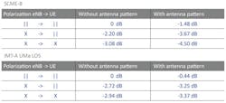
Advanced channel modeling: Because eight-antenna LTE systems use advanced antenna techniques, the modeled channels used for testing must replicate the physical characteristics of the channels used in those techniques. Failure to include every detail in the emulation results in an incorrect baseline for evaluating true system performance. For example, polarization affects the power of a signal received by a UE. Compared to the non-polarized case, the received signal has less apparent power. This loss, which is directly due to polarization, is dependent on the UE’s direction relative to the eNodeB antenna array.
The antenna pattern also has a direct effect on signal strength. The power of the received signal varies as a function of the direction of signal travel. Because each possible scenario has a unique set of angles-of-departure (AoDs), power again varies as a function of direction. The combination of antenna patterns and polarization makes this problem even trickier. The Table shows the power loss of different combinations in two-channel scenarios. An “X” in the table represents a cross-polarized antenna pair, while vertical bars (||) represent antenna elements with no polarization.
Dynamic scenarios: For a beamforming system, testing in a static (non-moving) condition is insufficient. Beamforming essentially involves two steps: estimating the direction of the UE and directing a beam toward it. When the UE moves, its direction (relative to the eNodeB antenna array) varies. This brings up two questions that are fundamental to understanding a system’s performance: How fast can the system track movement of the UE and how well does the system perform as a result? To answer those questions, one must test a beamforming system using dynamic scenarios that represent actual operating conditions.
Test Methodology
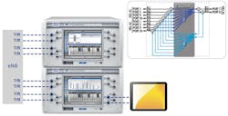
For reasons discussed earlier, an effective test methodology must address all of the challenges described: high numbers of reciprocal RF channels in a compact form factor, channel modeling that accounts for antenna patterns and polarization, and the ability to test beamforming in dynamic (motion) scenarios. The number of channels needed in bidirectional 8xN system testing presents an unprecedented challenge. Figure 3 is a graphical depiction of a modern system used for 8x2 bidirectional testing. A legacy channel emulator might occupy a 40U rack and require significant outboard RF hardware to achieve the same channel scenario.
As the technology advances, test-system requirements will only become more challenging and demanding. An example is dual-layer beamforming applications, which involve two UEs talking to the same eNodeB BTS from different physical positions. The required testing topology includes an 8x4 bidirectional MIMO channel (i.e, 16 RF channels with 32 digital channels). Another example is IRC. Testing IRC requires that the eNodeB BTS, which is the device under test (DUT) in this test case, receive signals from one “desired” UE and several interfering UEs and the testing accounts for the effects of fading.
The future also holds some challenging test scenarios as new techniques are developed and existing techniques are implemented in high-antenna-count MIMO systems. Multi-user MIMO (MU-MIMO), for instance, is not necessarily new. But testing it in the context of LTE’s MIMO UEs presents significant challenges, as complex techniques are “layered” together. In MU-MIMO, the system uses signal processing to take advantage of the spatial differences between multiple UEs. Another example is Coordinated Multi-Point (CoMP) transmission in LTE-A. This technique takes advantage of network redundancy in cases where the UE is connected to multiple eNodeB BTSs (typically at overlapping cell edges).
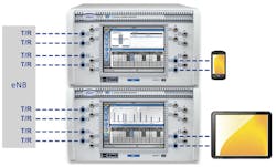
Figure 4 shows a typical compact setup for testing dual-layer beamforming, MU-MIMO, and CoMP with integrated bidirectional MIMO channels. The channel density of the integrated solution does more than just meet the challenges of limited lab space for a large number of RF channels. It also is a much more reliable platform in terms of both phase calibration and stability.
Geometric Channel Models
When it comes to testing advanced antenna techniques in LTE and LTE-A systems, correlation-based, legacy MIMO channel modeling is not a good fit. This traditional modeling approach does not capture the MIMO channel’s spatial characteristics or the effects of the advanced antenna techniques that were previously discussed.
Most correlation-based MIMO channel modeling is based on an assumption that the signal is omnidirectional as it leaves the transmit antennas and that it arrives at the receive antennas in the same way.4 This is not true in the case of MIMO beamforming.
To solve the problem, the research community came up with a new channel modeling approach known as Geometric Channel Modeling (GCM). In GCM, each signal path from each transmit antenna to each receive antenna is geometrically traced and summed together to generate the channel. This approach intrinsically supports antenna patterns and polarization. Given these properties, the GCM has been chosen to evaluate next-generation wireless technologies.3
Real-Time Fading
A real-time fading method generates channel data in real time as opposed to pre-calculating data and replaying it from buffer storage. There are two main drivers for real-time fading: to create true dynamic scenarios and to enable trial-and-error R&D troubleshooting. In dynamic or moving scenarios, channel parameters change over time. Real-time fading enables scripting of the channel parameters to mimic channel dynamics. Using a real-time fading engine, creating different types of UE movement for beamforming testing is simple and intuitive.
R&D testing requires flexibility in controlling the channel for troubleshooting. Together with geometric channel modeling, real-time fading allows an engineer to adjust one or more channel parameters and instantaneously get a response. This “trial-and-error troubleshooting” approach is common in product development and widely used in system performance tests.
As the industry pursues higher data rates to enable newer wireless applications, both the number of antennas used and the complexity of advanced antenna techniques are destined to increase. This trend poses significant challenges of testing LTE and LTE-A with advanced antenna techniques. It requires both new methodologies and new ways of thinking about test scenarios.
Eight-antenna systems quadruple the number of RF channels used in 2x2 MIMO systems. Yet researchers are already exploring techniques that will require eight times as many antenna elements as 2x2. Replicating reciprocal high-antenna-count test scenarios imposes a serious constraint in labs where space and other resources are constrained. Emerging advanced antenna techniques impose yet another challenge when compared to traditional channel modeling. Testing the system in dynamic scenarios is essential when the tester needs to fully understand the system’s performance.
An effective test methodology that meets these challenges must employ geometric channel modeling that supports advanced antenna techniques. It also has to run dynamic scenarios in real time. Finally, the test approach must reliably and efficiently create all of the details of bidirectional MIMO channel for eight-antenna systems—and do so in a compact form factor.
References:
1. R1-100708, “Proposal of Realistic Antenna Configuration for MU-MIMO and CoMP,” Vodafone, Deutsche Telekom AG, Orange, RAN1#59bis, Valencia, Jan. 2010.
2. R1-103376, “Antenna configurations for practical deployments,” AT&T, Orange, Vodafone, RAN1 #61, Montreal, May 2010.
3. Report ITU-R M.2135-1, “Guidelines for evaluation of radio interface technologies for IMT-Advanced,” ITU, Dec. 2009.
4. Douglas Reed, Fading Basics - Narrow Band, Wide Band, and Spatial Channels, http://www.spirent.com/Home/White-Papers/Mobile/Wireless%20White%20Paper%20101%20-%20Fading%20Basics.aspx, 2011.
Kang Chen is a Senior Applications Specialist at Spirent Communications. Prior to joining the company in 2007, Kang held senior engineering positions at Agilent and Alcatel. He earned a BEng from Chongqing University of Posts and Telecom, and an MSEE from Rutgers University, where he researched MIMO and cooperative communications.
About the Author
Kang Chen
Senior Applications Specialist
Kang Chen is a Senior Applications Specialist at Spirent Communications. Prior to joining the company in 2007, Kang held senior engineering positions at Agilent and Alcatel. He earned a BEng from Chongqing University of Posts and Telecom, and an MSEE from Rutgers University, where he researched MIMO and cooperative communications.
