Reducing ADC Quantization Noise
This file type includes high resolution graphics and schematics when applicable.
Analog-to-digital converters (ADCs) provide the vital transformation of analog signals into digital code in many systems. They perform amplitude quantization of an analog input signal into binary output words of finite length, normally in the range of 6 to 18 b, an inherently nonlinear process. This nonlinearity manifests itself as wideband noise in the ADC's binary output, called quantization noise, limiting an ADC's dynamic range. This article describes the two most popular methods for improving the quantization noise performance in practical ADC applications: oversampling and dithering.
To understand quantization noise reduction methods, first recall that the signal-to-quantization-noise ratio, in dB, of an ideal N-bit ADC is
SNRQ = 6.02N + 4.77 + 20log10 (LF) dB,
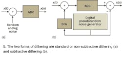
where:
LF = the loading factor measure of the ADC's input analog voltage level. (A derivation of SNRQ is provided in ref. 1.) Parameter LF is defined as the analog input root-mean-square (RMS) voltage divided by the ADC's peak input voltage. When an ADC's analog input is a sinusoid driven to the converter's full-scale voltage, LF = 0.707. In that case, the last term in the SNRQ equation becomes −3 dB and the ADC's maximum output-signal-to-noise ratio is
SNRQ-max = 6.02N + 4.77 −3 = 6.02N + 1.77 dB.
The SNRQ-max expression, which is common in the technical literature, explains why engineers use a rule of thumb of 6 dB/b for the SNR of an ADC.
As a practical matter, the SNRQ-max equation is unrealistically optimistic. First, the SNR expression represents an ideal ADC that is not available in the real world. Secondly, an ADC's input is rarely driven to full scale in practical applications. Real-world analog signals are often impulsive in nature and driving the ADC's input into saturation causes signal clipping that drastically reduces the ADC's output SNR. But, rather than examine worst-case scenarios, this article will assume a high-quality ADC that uses most of its input analog voltage range.
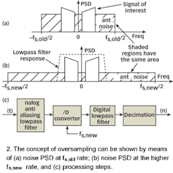
Assuming the 6 dB/b for ADC SNR, the next step is to consider the oversampling method as a possible approach to improve the SNRQ. The process of oversampling to reduce ADC quantization noise is straightforward. An analog signal is digitized at an fs sample rate that is higher than the minimum rate needed to satisfy the Nyquist criterion (twice the input analog signal's bandwidth) and then lowpass filtered.
Oversampling is based on the assumption that an ADC's total quantization noise power (variance) is the squared value of the converter's least-significant-bit (LSB) voltage divided by 12:
Total quantization noise power = σ2 = (LSB value)/12
Oversampling also assumes that the quantization noise values are truly random; this means that in the frequency domain, quantization noise has a flat spectrum. (This assumption is valid if the ADC is driven by an analog signal that covers a significant portion of the converter's analog input voltage range and is not highly periodic.)
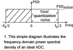
PSDnoise = 2/12>(1/fs) = (LSB value)2/12fs
which is measured in W/Hz.
The next question is: "How can the PSDnoise level be reduced?" The LSB value in the numerator could be reduced by using an ADC with additional bit resolution, which would reduce the LSB value and also reduce PSDnoise. But this is an expensive solution. A better approach is to increase the denominator with a higher sampling rate.
The improvement in signal-to-quantization-noise ratio, measured in dB, achieved by oversampling is:
SNRQ-gain = 10log10(fs,new/fs,old).
A derivation of the SNRQ-gain expression is provided in ref. 1. Because the number of bits of an N-bit ADC as a function of SNR is approximately SNR/6, the total number of effective bits is 10log(M)/6 + N, where M = fs,new/fs,old. This means that if the oversampling ratio M is 2, the effective number of ADC bits is Nos = 0.5 + N. With a factor of 2 oversampling, one-half bit is gained in the effective SNR. It can be shown that the oversampling ratio M required to achieve a specific number of K extra effective bits is given by M = 4K, so that the effective number of bits is Nos = K + N.
For example, if fs,old = 100 kHz, and fs,new = 400 kHz, the SNRQ-gain = 10log10(4) = 6.02 dB. Thus oversampling by a factor of 4 (and filtering), reduces the quantization noise by 1 b. Consequently, it is possible to achieve N+1-bit performance from an N-bit ADC, because signal amplitude resolution is gained at the expense of higher sampling speed. After digital filtering, the output signal can be decimated to the lower fs,old without degrading the improved SNR. Of course, the number of bits used for the lowpass filter's coefficients and registers must exceed the original number of ADC bits in order to benefit from the oversampling scheme. With the use of a digital lowpass filter, depending on the interfering analog noise in x(t), it's possible to use a lower-performance (simpler) analog anti-aliasing filter in Fig. 2(c) relative to the analog filter necessary at the lower sampling rate.
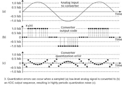
Dithering, the second technique used to minimize the effects of ADC quantization noise, is the process of adding noise to the analog signal prior to analog-to-digital conversion. As an example, consider digitizing the low-level analog sinusoidal signal shown in Fig. 3(a). The peak voltage of this signal just exceeds a single ADC's LSB voltage level, yielding the converter output x1(n) samples. Because of the high peak sinusoid voltage level, the x1(n) output sequence is clipped and this generates spectral harmonics in its spectrum, which are apparent as the periodicity of the quantization noise in Fig. 3(c).
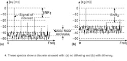
Figure 4(a) shows the spectrum of x1(n), in dB, where the spurious quantization noise harmonics are apparent. It's worthwhile to note that averaging multiple spectra does not make it possible to pull some spectral component of interest above those spurious harmonics levels. Because the quantization noise is highly correlated with the input sinewave—the quantization noise has the same time period as the input sinewave—spectral averaging will also raise the noise harmonic levels. But dithering will help.
Dithering results in a noisy analog signal that crosses additional converter LSB boundaries and yields a quantization noise that is much more random, with a reduced level of undesirable spectral harmonics Fig. 4(b)>. Dithering raises the average spectral noise floor but increases SNR2. Dithering forces the quantization noise to lose its coherence with the original input signal, which would then result in benefits from averaging, if desired.
Dithering is useful when digitizing low-amplitude analog signals, highly periodic analog signals (such as a sinewave with an even number of cycles in the sample time interval), and slowly varying (low-frequency or DC) analog signals. Figure 5(a) shows the standard implementation of dithering. The typical amount of random wideband analog noise used in this process, provided by a noise diode or noise generator ICs, has a peak-to-peak value of 1/3-to-1 LSB voltage level.
Wannamaker has shown that dither with a triangular probability distribution function (TPDF) results in quantization noise that has a constant average of zero and a constant (non-zero) power independent of the input signal characteristics.2 These are both highly desirable characters for quantization noise; the first guarantees that the output of the quantizer is, on average, equal to the input; the second guarantees that there will be no "noise modulation." Noise modulation occurs when the power of the quantization noise depends on, or is modulated by, the signal. This can be perceptually significant in audio signals and is generally undesirable.
For demanding high-performance audio applications, engineers have found this type of dither to be ideal. It can be generated by adding dither noise from two separate, and independent, uniformly distributed (also known as rectangular PDF) noise generators. The PDF of the sum of two independent noise sources is the convolution of their individual PDFs.3 Because the convolution of two rectangular functions is triangular, this dual-noise-source dithering scheme generates the required TPDF. The ideal TPDF dither noise has a peak-to-peak level of exactly two LSB voltage levels.
In the situation where the signal of interest occupies some well-defined portion of the full frequency band of 0 to fs/2, injecting spectrally shaped dither noise with a peak-to-peak value equivalent to 4 to 6 LSB voltage levels, with spectral energy that is outside that signal band, would be advantageous. Wannamaker gives sufficient (but not necessary) conditions on the character of this "filtered dither" that will guarantee the resulting quantization noise power is independent of the signal, and shows that the resulting dither noise spectrum will be similar in shape to the quantization noise spectrum with the addition of a constant (in frequency) noise power.4 It should be remembered, however, that the dither signal can't be too narrowband, like a sinewave. Quantization noise from a sinewave signal would generate additional spurious harmonics! That narrowband dither noise can then be removed by follow-on digital filtering.
The type of dithering discussed here is known as "non-subtractive dither" (NSD). Figure 5(b) illustrates another method of applying dither known as "subtractive dither" (SD). An SD system has all the benefits of dither (it randomizes the quantization noise) but none of the disadvantages (it does not increase the overall noise power). Wannamaker shows how subtractive dither of the proper character will result in a total quantization noise that is spectrally white and uniformly distributed. Software that models these ADC quantization noise reduction schemes is available at: www.DigitalSignalLabs.com.
EDITOR'S NOTE
Some of the content in this article is based on the text, Understanding Digital Signal Processing, 2nd ed., by Richard Lyons, Prentice-Hall, Upper Saddle River, NJ, 2004.
REFERENCES
- R. Lyons, Understanding Digital Signal Processing, 2nd ed., Prentice Hall, Upper Saddle River, NJ, 2004.
- R. Wannamaker et al., "A Mathematical Theory of Non-Subtractive Dither," IEEE Transactions on Signal Processing, Vol. 48, February 2000, pp. 499-516.
- Y. Viniotis, Probability and Random Processes for Electrical Engineers, McGraw-Hill, New York, 1998.
- R. Wannamaker, "The Theory of Dithered Quantization," Ph.D. Thesis, Dept. of Applied Mathematics, Univ. of Waterloo, Waterloo, ON, Canada, July 1997.
