Design An X-Band Vivaldi Antenna
Download this article in .PDF format
This file type includes high resolution graphics and schematics when applicable.
Antennas are essential to highfrequency communications and electronic systems for radiating or receiving electromagnetic (EM) energy. Although there are many types of antennas, they all operate according to the same basic EM principles. The basic behavior of an antenna can be described by its wave field strength, polarization, and direction of propagation.1 Key requirements in applications such as airborne radar and communications systems include high efficiency, wide bandwidth, light weight, small size, and simplicity.2
The tapered slot antenna (TSA), which was introduced by Gibson in 1979,3 is well suited to meeting these requirements. In 1986, the simple case of a TSA without a substrate was first analyzed,4 with more advanced analysis methods to follow. Many of the early TSA experiments were conducted with electronic design automation (EDA) software design and analysis tools, such as the High Frequency Structure Simulator (HFSS) from Ansoft (www.ansoft.com) and CST Microwave Studio from Computer Simulation Technology (www.cst.com). But for all this research, there has been insufficient study of a practical TSA design, a highfrequency single-sided exponential Vivaldi antenna, as will be presented here.
The Vivaldi antenna designed for the present study targets use at X-band frequencies, nominally from 8 to 12 GHz.5 The antenna was modeled and simulated with the Advanced Design System (ADS) EDA software tools from Agilent Technologies (www.agilent.com) using method of moments (MoM) analysis. This method is based on the exact Green's function; the MoM-based procedure used in ADS calculates the reflection coefficient and the unknown electric currents on the antenna. It then computes reflection coefficients, the convergence of basic functions and current distributions, and the far-field radiation behavior. Some of these parameters are validated by high-frequency measurements with a microwave vector network analyzer (VNA) and a spectrum analyzer.
Before attempting to design a Vivaldi antenna, its characteristics should be well understood. Its basic construction, operating principles, radiation patterns, types of TSAs, polarization, and feed techniques must be considered and studied before proceeding with the design and fabrication of a Vivaldi antenna. To understand the design of such an antenna, it will first be simulated using modern high-frequency EDA tools and then fabricated and measured to compare the performance with simulations.
A Vivaldi antenna is a useful configuration because of its simplicity, wide bandwidth, and high gain at microwave frequencies. In general, it has an end-fire radiation pattern, making it a member of the class of continuously scaled, gradually curved, slow leaky end-fire traveling-wave-type antennas. 6 At different frequencies, different parts of a Vivaldi antenna radiate, while the size of the radiating part is constant in wavelength. As such, the Vivaldi antenna has theoretically unlimited operating frequency range, with constant beamwidth over this range. Terms like "tapered-notch," "flared-slot," and "tapered-slot" antennas have been used interchangeably with Vivaldi antennas in the literature. These antennas consist of a tapered slot etched onto a thin metal film, either with or without a dielectric substrate on one side of the film.
Along with their efficiency and lightweight characteristics, TSAs such as the Vivaldi antenna are attractive because they can work over wide bandwidths and produce a symmetrical end-fire beam with appreciable gain and low sidelobes.7Figure 1 shows the basic construction of a Vivaldi antenna, with WE the input slot width, WA the slot width at the radiating area, and Wo the output slot width.
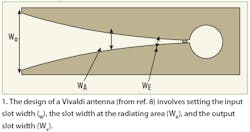
A Vivaldi antenna has two areas for propagating and radiating:
1. a propagating area defined by WEA and 2. a radiating area defined by WAo.
A Vivaldi antenna is a "surfacetype" traveling-wave antenna. The EM waves travel down the curved path of the flare along the antenna. In the region where the separation between the conductors is small compared to the free-space wavelength, the waves are tightly bound. As the separation increases, the bond becomes progressively weaker and the waves are radiated away from the antenna. This occurs when the edge separation is greater than one-half wavelength.
Traveling-wave propagation occurs along a Vivaldi antenna's structure because of the phase velocity of its EM waves is less than the velocity of light in free space. As a result, a Vivaldi antenna is characterized by radiation in the end-fire direction as shown in Fig. 2.

The limiting case of phase velocity relates to the case of an antenna with air dielectric and consequently the beamwidth and the sidelobe level are considerably greater than for the case with dielectric substrate present. Also, the phase velocity and the guide wavelength vary with the change in the thickness, dielectric constant, and taper design.8
A TSA can be designed with a variety of taper profiles. Planar TSAs have two common features: the radiating slot acts as the ground plane for the antenna and the antenna is fed by a balanced slotline. Challenges in designing a planar TSA include using a low-dielectric-constant substrate material for the antenna and achieving the proper impedance match for the slotline. By using a low-dielectricconstant substrate, a relative high impedance results for the slotline. This makes it difficult to achieve an impedance match if a microstrip feed is used. As a result, the microstrip-toslot transition will limit the operating bandwidth of a TSA.
Studies have been performed to investigate the effect of the curvature of the mounting structure on different types of TSAs. The experiment showed that the curvature of tapered profile has a significant impact on the gain, beamwidth and bandwidth of TSAs.9 In fact, the feed generally determines the high-frequency limit while the aperture size determines the low-frequency limit.10 Thus, a properly designed feed structure is essential for maximizing the bandwidth of a TSA. Although microwave integrated circuits (MICs) are typically realized with microstrip, a slotline is the optimum transmission medium for a TSA feed. The transition from microstrip to slotline should be compact and with loss in order to couple microwave signals from the antenna to a planar microstrip circuit. Many feed techniques are available, with the most common approaches being coaxial feed lines and microstrip feed lines.
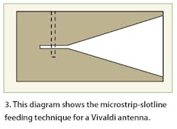
A microstrip-to-slotline transition offers many advantages compared to other feed mechanisms. This transition can be easily fabricated by a conventional photo-etching process. In addition, two-sided printed-circuit boards (PCBs) can be fabricated with microstrip on one side and slotline on the other to achieve a compact transition. This type of transition was used with the Vivaldi antenna in this report (Fig. 3).
Unbalanced-to-balanced transformation
The microstrip lines widely used in microwave PCBs are unbalanced lines, although a Vivaldi antenna requires a feed with a slotline transmission line, which is balanced. The balun required for the unbalanced-to-balanced transformation must operate over a frequency range of at least two octaves, and up to several octaves. Preferably, the balun would be frequency independent. 6 To demonstrate the effectiveness of TSA designs, a Vivaldi antenna was chosen from other possible designs, due to the wealth of existing research on this configuration. In designing any antenna, the choice of dielectric substrate is critical. The choice of substrates is large, with a wide range of characteristics and dielectric constants among those choices. For this experimental Vivaldi antenna, it was preferable to fabricate the transition and the Vivaldi antenna on a low dielectric constant substrate, and to avoid the use of a drilled short hole. The experimental antenna was fabricated on RO4003C substrate material from Rogers Corp. (www.rogerscorporation.com), which has a dielectric constant of 3.38. Agilent's ADS software was used to optimize the design for use from 8 to 12 GHz.
A microstrip-to-slotline transition was chosen for the Vivaldi antenna because of its many benefits compared to other approaches. One of the main advantages is that this type of transition can be easily fabricated by normal photo-etching processes, making it possible to realize two-sided PCBs with microstrip on one side and slotline on the other side.
Kayani et al. proposed a simple, compact Vivaldi antenna in 2005.11 Their single-sided design employed stripline-to slot-line coupling as shown in Fig. 4. The main advantage of this design is that the antenna can be made smaller compared to an antipodal Vivaldi antenna. In addition, because of the small size of the antenna, it features a relatively short simulation time when using computer- aided-design (CAE) software tools. Figure 4 shows the double-sided Vivaldi antenna for operation from 8 to 12 GHz.

The length is 7.48 cm and the width is 2.08 cm. The width of microstrip line is 0.29 cm. The diameter of the circular slot stub is 1 cm and the slotline gap is 0.08 cm.
The design and simulation process using the Momentum EM analysis tool from Agilent's ADS software suite consists of numerous steps:
1. Create the physical design for a high-frequency Vivaldi antenna.
2. Choose the desired Momentum operating mode for simulating the Vivaldi antenna.
3. Define the required substrate material and its characteristics.
4. Solve for the substrate parameters by precomputing the substrate used.
5. Assign antenna ports and define their properties.
6. Set up and generate a circuit mesh.
7. Set up and simulate the performance of the Vivaldi antenna.
8. View the S-parameters and radiation pattern results.
The actual steps applied to creating and simulating the Vivaldi antenna with Momentum13 software will be detailed in Part 2 of this article series, in next month's (August 2008) issue of Microwaves & RF. Part 2 will provide a comparison of measurements performed with commercial test equipment in the 9-GHz band and simulations on the Vivaldi antenna performed with the Agilent Momentum planar EM simulation software from Agilent Technologies.
This ends Part 1 of this article on Vivaldi antenna design, to be concluded in the August 2008 issue.
See Associated Table
REFERENCES
1. N. Blaunstein N. and C. Christodoulou, Radio Propagation and Adaptive Antennas for Wireless Communication Links, Wiley, Hoboken, NJ, 2007.
2. H. Oraizi and S. Jam, "Optimum Design of Tapered Slot Antenna Profile," IEEE Transactions on Antennas & Propagation, vol. 51, No. 8, 2003, pp. 1987-1995.
3. P. J. Gibson, "The Vivaldi aerial," Proceedings of the 9th European Microwave Conference, 1979, pp. 103-105.
4. R. Janaswamy, D. H. Schaubert, and D. M. Pozar, "Analysis TEM mode linearly tapered slot antenna," Radio Science, Vol. 21, 1986, pp. 797804.
5. J. Wales and L. Sanger, citing Internet sources, 2001: http://en.wikipedia.org/wiki/X_band.
6. E. Gazit, "Improved design of the Vivaldi antenna," IEE Proceedings, Vol. 135, Part H, No. 2, 1988, pp. 89-92.
7. H. Y. Wang, D. Mirshekar-Syahkal, and I. L. Dilworth, "A Rigorous Analysis of Tapered Slot Antennas on Dielectric Substrates," 10th International Conference on Antennas and Propagation, Conference Publication No. 436, University of Essex, UK, 1997.
8. R. Rajaraman, "Design of a Wideband Vivaldi Antenna Array for the Snow Radar," Master's thesis, The University of Kansas, India, 2004.
9. R. Q. Lee and R. N. Simons, "Effect of Curvature on Tapered Slot Antennas," Antennas and Propagation Society International Symposium, AP-S. Digest, Vol. 1, 1996, pp. 188-191.
10. J. P. Weem, Z. Popovic, and B. M. Notaros, "Vivaldi antenna arrays for SKA," Antennas and Propagation Society International Symposium, Vol.1, 2000, pp. 174-177.
11. J. K. Kayani, A. B. Rashid, and A. Naveed, "Design and Testing of Vivaldi Antenna for UWB Application," Fourth International Bhurban Conference on Applied Sciences and Technology, Bhurban, Pakistan, 2005.
12. J. D. S. Langley, P. S. Hall, and P. Newham, "Balanced antipodal Vivaldi antenna for wide bandwidth phased arrays," IEE Proceedings -- Microwaves, Antennas and Propagation, 1996, Vol. 143.
13. Agilent Technology (www.agilent.com), Momentum planar electromagnetic simulator, Advanced Design System, 2005.
This file type includes high resolution graphics and schematics when applicable.
