Compensating For DGS Filter Loss
Dr. Ahmed Boutejdar and Dr. Abbas Omar
Novel circuit design elements such as defected-ground-structure (DGS) resonators and electromagnetic-band-gap (EBG) structures have helped shrink the size of microstrip circuits, including filters and antennas. In particular, success has been achieved with DGS elements, although using such elements can increase loss. To better understand the causes for those losses, three methods were applied to the study of an experimental arrowhead DGS element used in a compact bandpass filter. A compensation approach was developed by embedding a metal box where the DGS resonator will be placed. An equivalent circuit for the DGS resonator was extracted by using the field distribution and analysis method, with circuit simulations performed by means of Microwave Office simulation software from AWR Corp. and measurements made with the help of a model HP 87533 vector network analyzer from Agilent Technologies with frequency range of 4 to 40 GHz. As the results will show, this approach with an embedded metal box can significantly minimize the loss due to the use of a DGS structure in the case of this bandpass filter. DGS and EBG structures have both been instrumental in reducing the size of various circuits used in wireless communications, including filters and antennas. The DGS slot, which has evolved from an EBG structure, is realized by etching a pattern in the backside metal ground plane of a microstrip printed-circuit board (PCB). DGS elements are essentially small and wide etched areas in the backside metal ground plane, which gives rise to an increase in the effective capacitance (C) and inductance (L), respectively, of transmission lines on the other side of the circuit board.1-7 The increased equivalent inductive component of the microstrip line with a DGS produces a slow-wave property.8-12 A DGS is formed of two wide etched areas connected through a narrow slot-channel. The total area corresponds to an equivalent LC circuit. To best understand how to apply these structures in practical circuits, such as a bandpass filter, two methods will be explored for the study of DGS and EBG structures: a field distribution method and an extraction method.
Numerous designs have been achieved with the aid of a DGS approach,12-21 but issues with excessive loss were always neglected by the researchers. Discrepancies in their results because of loss were always accepted without considering possible corrections. To explore corrections for the loss of DGS circuit elements, an arrowhead-shaped DGS element will be used in this study, as shown in Fig. 1. By developing an equivalent-circuit model for that DGS element, and examining the causes of additional loss from the DGS element, it may be possible to develop a correction for the loss using a metal box technique.
Figure 2 provides a two-dimensional (2D) view of a microstrip transmission line with the experimental DGS resonator, etched on metallic ground plane. A linewidth with w = 1.9 mm was used to achieve a characteristic impedance (Z0) of 50 Ω. For fabricating the filter and for modelling purposes in the computer simulations, a RO4003 laminate from Rogers Corp. with the printed-circuit-board (PCB) material. It had a thickness of 0.813 mm and relative dielectric constant (εr) of 3.38 in the z direction (thickness) at 10 GHz.
The parameters of the experimental arrowhead-shaped DGS resonator were as follows: d = 5 mm, s = 0.6 mm, h = 5 mm, X = 5 mm, and W = 1.9 mm. The experimental arrowhead-DGS resonator and its dimensions are shown in Fig. 2. A transmission line with characteristic impedance of 50 Ω was placed at the top plane. The arrowhead-shaped DGS slot in the ground plane, excited by the 50-Ω transmission line, acts like a parallel inductive-capacitive (LC) resonant circuit.
In developing this model for the filter, radiation and surface wave losses were also taken into consideration by including parallel resistance R in the equivalent circuit, as shown in Fig. 3. Figure 3 and Figure 4 represent the equivalent circuit of the experimental arrowhead-shaped DGS resonator and its corresponding S-parameters. To derive the equivalent-circuit parameters, the S-parameters of a unit DGS cell can be calculated at the reference plane by means of electromagnetic (EM) simulation. The values of R, L, and C can be computed using the following expressions.
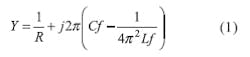
The equivalent impedance of the parallel resonance is given by Eqs. 1 and 2:
Using the circuit model in Fig. 3 and circuit theory, this yields Eq. 3:
At the 3-dB cutoff frequency point, fc, and supposing that R >> Z0, this yields results in Eqs. 4 and 5:
Using Eq. 5, the capacitance and inductance of the equivalent-circuit model can be given by Eqs. 6 and 7:
Resistance R in the equivalent-circuit model is best fitted around the resonant frequency. In this case, the equivalent impedance Zs = R and the transmission loss S21 is found from Eqs. 8 and 9:
The object of this short investigation is to verify the dependence of the equivalent-circuit elements (capacitance and inductance) on the surface current as evidenced by the distributed EM field. Simulation results are shown in Fig. 5. The microstrip structure is divided into two regions. In region II, the electric field is highly concentrated in the gap; hence, any change in the dimensions of the gap will impact the effective capacitance of the structure. In region I, the electric field nearly vanishes. This means that the arrowhead DGS does not affect the effective capacitance of the filter structure. On the other hand, the current is distributed throughout the whole structure. Therefore, any change in the length of the arrowhead site strongly affects the magnetic-field distributionand hence the surface current, which in turn leads to a change in the effective inductance of the structure. Therefore, region II corresponds to a capacitance and region I corresponds to an inductance. The full structure corresponds then to an LC-resonator.
Page Title
Optical measurements performed on circuit structures using a model IP200 measurement system at the Institute for Manufacturing and Quality Assurance at University of Magdeburg confirmed the existence of unwanted strips at the edges of the RF structures (Fig. 6, Fig. 7, and Fig. 8), but their widths were not constant, fluctuating between 20 to 200 m. A comparison between measured and simulated S-parameter shows no dependence between two curves, or in connection with physical features, from an investigation of manufacturing defects (Fig. 9). The comparison between the physical dimensions of simulated and measured filter structures shows that deviations are around 0.04 mm. This value is within the tolerance range of the measuring instrument. Based on these results, it can be concluded that the features of the filters have been etched with sufficiently high accuracy. This would indicate that there are other causes for deviations between the measured and simulated data with the exception of manufacturing defects.
Thermal losses, caused by the resistance, have no significant influence on the resonator results.17 To investigate these losses and their influence on the deviations between measured and simulated results, an arrowhead-DGS resonator with a specific resonant frequency was designed and simulated using the Microwave Office circuit simulator.18 These studies showed that a change in resistance values affect the reject band but not on the deviations between measured and simulated results. Such experiments have been performed in our previous work and can be seen in ref. 17.
Figure 10 shows how the electric field lines are spread partially in the circuit substrate and partially in the air above the substrate, which leads to an increase in loss. In contrast to the previous case, the circuit's field lines will be suppressed and concentrated within a limited space by using a metal box. Often, a filter that had been fabricated was measured without any shielding.9 To achieve a closer approximation of the simulation results (deviation compensation) and simultaneously compensate for radiation losses, a fabricated filter was enclosed in a metal box while measurements were performed. The metal box was properly dimensioned so that its resonance frequency, fr, box, equals the unwanted second resonant frequency of the filter (suppressing the second harmonics).
By using these corrections and applying the "metal-box" method, a DGS bandpass filter with arrowhead-shaped resonators was designed, simulated, and fabricated for a target bandwidth of 800 MHz at a center frequency of 6.8 GHz. Figure 11 and Figure 12(a, b) show a schematic-circuit three-dimensional (3D) view and the fabricated filter, respectively. Figures 13(a) and (b) provide a comparison of the simulated and measured results. Using the metal box shifted f0 from 6.5 to 7.3 GHz, or a frequency difference, df, of 800 MHz. Normally radiated energy would be reflected through the metal box, leading to the discrepancy shown in Fig. 13.
In summary, an arrowhead-shaped DGS resonator can be an effective circuit element in the design of a compact microwave filter when all losses are taken into account. As was discovered, the use of a DGS circuit with a metallic box leads to a good coupling effect and minimizes the radiation of the filter structure. In fact, filter performance can be controlled by changing the dimensions of the metal box structure. By accounting for all losses, good agreement was achieved between measured and simulated results.
Acknowledgments
The author is grateful to the Deutsche Forschungs-gemein schaft DFG, the central of research funding organization in Germany. The author is also grateful to administrator Mr. D. Winkler for his computer assistance and Mr. Dempewolf, the laboratory manager of the Institute for Electronics, Signal Processing and Communication (IESK) at the University of Magdeburg, Germany.
References
- A. Rahman, A.K. Verma, A. Boutejdar, and A. Omar, "Control of band stop response of hi-lo microstrip lowpass-filter using slot in ground plane," IEEE Transactions on Microwave Theory & Techniques, Vol 52, No. 3, March 2004, pp. 1008-1013.
- A. Boutejdar, A. Elsherbini, Liu Haiwen Liu, et al., Improvement of microstrip lowpass filters' characteristics using an optimized number of new multi-ring defected ground structures," Microwave & Optical Technology Letters, Vol. 49, No. 12, December 2007, pp. 3074-3078.
- J.S. Lim, C.S. Kim, Y.T. Lee, D. Ahn, and S. Nam, "A new type of low pass filter with defected ground structure," in the Proceedings of the 32nd European Microwave Conference, 2002. pp. 32-36.
- A. Boutejdar, A. Elsherbini, and A. Omar, "Design of a novel ultrawide stopband lowpass filter using H-defected ground structure," Microwave & Optical Technology Letters, Vol. 50, No. 3, March 2008, pp. 771-775.
- A. Boutejdar, M. Makkey, A. Elsherbini, et al., "Design of compact stop-band extended microstrip low-pass filters by employing mutual-coupled square-shaped defected ground structures," Microwave & Optical Technology Letters,Vol. 50, No. 4, April 2008, pp. 1107-1111.
- H. Lung-Hwa and C. Kai, "Compact elliptic-function low-pass filter using microstrip stepped-impedance hairpin resonators," IEEE Transactions on Microwave Theory & Techniques, Vol. MTT-27, 1979, pp. 44-50.
- C.F. Chen, T.Y. Huang, C.H. Tseng, R.B. Wu, and T.W. Chen, "A Miniaturized Multilayer Quasi-Elliptic Bandpass Filter With Aperture-Coupled Microstrip Resonators," IEEE Transactions on Microwave Theory & Techniques, Vol. 53, No. 9, 2005.
- A. Boutejdar and A. Omar, "New low-pass filter design by using compensated microstrip capacitor and coupled meander defected ground structure (DGS)," Recent Patents Electrical Engineering Journal, Vol. 3, No. 1, 2010, pp. 30-34.
- Y.K. Kim, D.H. Kwon, K.H. Kim, J.W. Kim, S.W. Hwang, and J.W. Park, "Characterization and Modeling of a Microstrip Bandpass Filter with Shielding Effect Considered," Journal of the Korean Physical Society, Vol. 41, No. 6, December 2002, pp. 861864.
- A. Boutejdar, A. Elsherbini, and A. Omar, "Method for widening the reject-band in low-pass/band-pass filters by employing coupled C-shaped defected ground structure," IET Microwave Antennas & Propagation,Vol. 2, No. 8, December 2008, pp. 759-765.
- Xun Luo, Jian-Guo Ma, and Er-Ping Li, "Hybrid Microstrip/DGS Cell for Filter Design," Microwave & Microwave and Wireless Component Letters, Vol. 21, No. 9, October 2011, pp. 531-533.
- Ahmed Boutejdar, Amari Smain, and Omar Abass, "A Novel Compact J-Admittance Inverter-Coupled Microstrip Bandpass Filter Using Arrowhead-Shape As Defected Ground Structure," Microwave & Optical Technology Letters, Vol. 52, No. 1, January 2010, pp. 34-38.
- A. Batmanov, A. Boutejdar, E. Burte, and A. Omar, "New Coplanar Low-Pass Filter Using Defected Ground Structure (DGS)," (book chapter), Ultra-Wideband, Short-Pulse Electromagnetics 9, Springer, New York, 2010, pp. 1657-1664.
- Anatoliy Batmanov, Ahmed Boutejdar, Edmund Burte, and Abbas Omar, "Design of Compact Low-Pass Filters Using Cascaded Arrowhead DGS Sots for Microstrip Line and CPW Applications," Proceedings of the IWMF 2009 International Workshop on Microwave Filters, Toulouse, France, November 16-18, 2009.
- M. Li, L. Haiwen, Ahmed Boutejdar, Shuxin, and F. Tong, "Novel Microstrip Bandpass Filter With Slotted Hexagonal Resonators And Capacitive Loading," Proceedings of the 38th European Microwave Conference (EuMC), Amsterdam RAI, Amsterdam, The Netherlands Niederland, October 27-31, 2008.
- Ahmed Boutejdar, Adel Rahman, Anand Verma, Galal Nadim, and Abbas Omar, "Improved circuit model for DGS based lowpass filter," in Proceedings of the Conference on Antennas and Propagation Society International Symposium, APS 2004, Monterey, CA, April 2004, pp. 998-1001.
- Mohamed Awida, Ahmed Boutejdar, Amr Safwat, Hadia El-Hannawy, and Abbas Omar, "Multi-Bandpass Filters Using Multi-Armed Split Ring Resontors with Direct Feed," in Proceedings of the Conference on IEEE MTT-S International Microwave Symposium 2007, Honolulu, HI, June 2007.
- Amir Arbabi, Ahmed Boutejdar, and Abbas Omar, "Increase of Characteristic Impedance of Microstrip Line Using a simple Slot in Metallic Ground Plane," in Proceedings of the Conference on HUT-ICCE2006 First International Conference on Communications and Electronics, Hanoi-Vietnam, October 2006.
- Microwave Office high-frequency simulation software, Applied Wave Research (AWR), www.awrcorp.com.
- N.C. Karmakar, S.M. Roy, and I. Balbin, "Quasi-Static Modeling of Defected Ground Structure," IEEE Transactions on Microwave Theory & Techniques, Vol. 54, No. 5, May 2006, pp. 2160-2168.
- J.S. Park, J.H. Kim, J.H. Lee, S.H. Kim, and S.H. Myung, "A novel equivalent circuit and modeling method for defected ground structure and its application to optimization of a DGS lowpass filter," Proceedings of the IEEE MTT-S International Microwave Symposium Digest, Vol. 1, June 2002, pp. 417-420.
DR. ENG. AHMED BOUTEJDAR, Researcher, Assistant Professor, Chair of Microwave and Communication Engineering University - Otto-von-Guericke University Magdeburg, Magdeburg, Germany; +49 3916720069, FAX: +49 3916720051, e-mail: [email protected].
