UWB Bandpass Filter Features Dual Notches
This file type includes high resolution graphics and schematics when applicable.
In 2002, the U.S. Federal Communications Commission (FCC) authorized the use of license-free ultrawideband (UWB) signals from 3.1 to 10.6 GHz. The move swung the door open to applications such as high-data-rate wireless communications, high-accuracy radars, imaging systems, and indoor systems.1
As one of the essential components of a UWB system, UWB bandpass filters (BPFs) garner lots of attention. A number of the many methods already presented to design UWB BPFs2-9 have taken on the challenges of supporting such a wide bandwidth. These methods include multiple-mode-resonator (MMR) filters,2,3 defected-ground-structure (DGS) filters,4,5 multilayer-coupled-structure filters,6,7 and cascaded low- /high-pass filters.8,9
However, UWB systems cover very broad bandwidths, subjecting them to interference from many existing wireless networks, including 5.8-GHz wireless-local-area-network (WLAN) systems and some 8-GHz satellite-communications (satcom) systems. To minimize the effects of interference, UWB BPFs with multiple notched bands are needed to reject the unwanted signals.10-17
One step toward achieving desired band-notched performance levels in UWB systems involved evaluation of stepped-impedance resonators.10-13 Unfortunately, these designs came up with only one notched band. As a possible solution, double open-circuit stubs were embedded into the middle layer of broadside-coupled, stepped-impedance resonators,14 with folded stepped-impedance resonators vertically coupled to the second layer of the multiple-layer circuit design.15
This approach produced two notched bands in a UWB BPF circuit. However, using such a multiple-layer circuit structure would ultimately lead to increased fabrication costs and incompatibility with typical existing microwave integrated circuits (MICs). Some work yielded BPFs with dual notched bands,16,17 but these filters offered relatively low selectivity and less-than-ideal rejection levels for the notched filter bands.
Seeking improvements, engineers designed and developed a new compact UWB BPF with dual notched bands and good selectivity. An initial E-shaped multiple-mode resonator (EMMR) was used to create a basic UWB BPF with a pair of transmission zeros appearing in the lower and upper stopbands to improve skirt selectivity. Then, two parallel U-shaped slots (USSs) were etched into the initial EMMR to obtain the dual notched bands with a high degree of adjustment freedom, but without increasing filter size. The UWB BPF features notched bands centered at 5.8 and 8.0 GHz. To verify the validity of the design approach, measurements and computer-simulated results are presented for comparison.

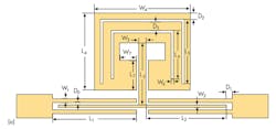
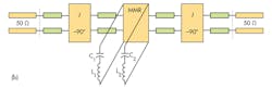
Figures 1(a) and (b) illustrate the configuration of the proposed UWB BPF with dual notched bands and its equivalent circuit network, respectively. Figure 1(a) shows two microstrip interdigital coupled lines and an initial EMMR with two embedded parallel U-shaped slots (USSs). The microstrip interdigital coupled lines provide sufficiently strong coupling in the desired UWB band. As seen in the equivalent-circuit network for the proposed UWB filter (Fig.1(b)), it’s possible to model the microstrip interdigital coupled lines as two single transmission lines at two sides and a J-inverter susceptance in the middle. The two parallel USSs etched into the initial EMMR can be considered as two shunt-series resonant branches.
Adjusting the length of each USS, which is about one-half the wavelength of the desired frequency, tunes the center frequency of a notched band. Essentially, each USS is a half-wavelength resonator. To postulate the resonant frequency, refer to Eqs. 1 and 2:
fnotch-lower = c/[λnotch-even(εeff)0.5] = c/[(2W5 + 4L5)(εeff)0.5] (1)
fnotch-upper = c/[λnotch-even(εeff)0.5] = c/[(2W6 + 4L6)(εeff)0.5] (2)
where:
fnotch is the center frequency of the notched band;
λnotch is the corresponding wavelength;
εeff is the effective dielectric constant;
and c is the speed of light in free space.
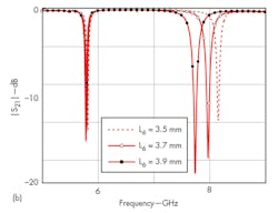
To validate the resonant properties, the frequency characteristics of USSs with various dimensions were simulated with Version 11.0 of the High Frequency Structure Simulator (HSFF) electromagnetic (EM) simulation software from Ansoft/ANSYS (Fig. 2). The frequency locations of the lower notched bands move downward in frequency with increases in the dimensions of L5.
However, with decreases in the dimensions of parameter L6, only the resonant frequency of the upper notched band moves upward. To obtain the desired frequencies for the notches, fnotch-lower can be tuned by adjusting the length of L5 varying the length of parameter L6 controls fnotch-upper. The two notched bands can be independently tuned for desired notch frequencies.
The UWB BPF with dual notched bands was fabricated on RT/duroid 5880 printed-circuit-board (PCB) material from Rogers Corp. The PCB material features a relative dielectric constant of 2.20 in the z-axis, measured at 10 GHz, with a thickness of 0.813 mm and loss tangent of 0.0027.
The optimal structural parameters for the UWB filter circuit (as illustrated in Fig. 1) were selected as follows: L1 = 7.0 mm; L2 = 6.7 mm; L3 = 5.0 mm; L4 = 6.2 mm; L5 = 5.1 mm; L6 = 3.8 mm; L7 = 2.4 mm; W1 = 0.3 mm; W2 = 0.2 mm; W3 = 0.6 mm; W4 = 8.0 mm; W5 = 7.0 mm; W6 = 4.8 mm; W7 = 1.4 mm; D0 = 0.1 mm; D1 = 0.5 mm; D3 = 0.6 mm; and D4 = 0.1 mm.
This file type includes high resolution graphics and schematics when applicable.
Measuring the BPF
This file type includes high resolution graphics and schematics when applicable.
The fabricated UWB BPF with dual notched bands was measured with the 8722ES vector network analyzer (VNA) from Agilent Technologies. The simulated and measured S-parameters for the filter are in close agreement (Fig. 3). As The UWB BPF’s passband, which ranges from 3.2 to 10.3 GHz, has an upper stopband with 10-dB attenuation through 17 GHz. Return loss is better than 15 dB across most of the passband.

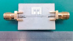
For the two notched bands, insertion losses of more than 15 dB were measured at 5.8 and 8.0 GHz. The measured 3-dB fractional bandwidths (FBWs) for these two notched bands were 1.1% at 5.8 GHz and 1.2% at 8.0 GHz. Two transmission zeros were achieved around 2.3 and 11.6 GHz, improving the frequency selectivity and out-of-band performance. Some deviations between the measurements and the simulations were expected, due to factors such as reflections from the SMA connectors and the finite loss capabilities of the substrate circuit material. Figure 4 shows the fabricated UWB BPF with dual notched bands, which measures a mere 20 × 27 mm2.

The microstrip UWB BPW offers good passband and rejection-band performance levels in a fairly compact structure. It provides tenability of the notch bands and should be an attractive option for modern UWB communications systems, thanks to its simple structure, compact size, planar implementation, and high performance.
Acknowledgments
This work was supported by the National Natural Science Foundation of China under Grant No. 51164033, the Jiangxi province Ground Plan of Science and Technology for Institution of Higher Education Grant No. KJLD12050, and the Jiangxi Province Science and Technology supporting project No. 20123BBE50116. It also received support from the Jiangxi province Natural Science Foundation of China under Grant No. 20132BAB206021. Other support came by way of the Scientific Research Fund of Jiangxi province Nos. 12747, 11739, and 12748; the Scientific Research Fund of Hunan Provincial Education Department under Grant No. 13C022; and the Hunan Province Nature Science Foundation of China under Grant No. 14JJ2118.
Huazia Peng, Associate Professor
School of Mechanical and Electrical Engineering, Nanchang University, Nanchang 330031, China and School of Electrical and Information Engineering, Hunan University of Technology (HUT), ZhuZhou 412007, People's Republic of China
Yufeng Luo, Professor
School of Mechanical and Electrical Engineering, Nanchang University, Nanchang 330031, People's Republic of China
Junding Zhao, Engineer
Nanjing Changfeng Aerospace Electronic Technology Co., Ltd., Nanjing 210000, China and Ministerial Key Laboratory of JGMT, Nanjing University of Science and Technology (NUST), Nanjing 210094, People's Republic of China
References
1. United States Federal Communications Commission (FCC, www.fcc.gov), Revision of Part 15, the Commission’s Rules Regarding to Ultra-Wide-Band Transmission System, First Note and Order Federal Communication Commission, ET-Docket 98–153, 2002.
2. L. Zhu, S. Sun, and W. Menzel, “Ultra-wideband (UWB) bandpass filters using multiple-mode resonator,” IEEE Microwave & Wireless Component Letters, Vol. 15, No. 11, 2005, pp. 796–798.
3. L. Qiang, Y.-J. Zhao, Q. Sun, W. Zhao, and B. Liu, “A compact UWB HMSIW bandpass filter based on complementary split-ring resonators,” Progress In Electromagnetics Research, Vol. 11, 2009, pp. 237–243.
4. J.-K. Lee and Y.-S. Kim, “Ultra-wideband bandpass filter with improved upper stopband performance using defected ground structure,” IEEE Microwave & Wireless Component Letters, Vol. 20, No. 6, 2010, pp. 316–318.
5. M. Shobeyri and M.-H. Vadjed-Samiei, “Compact ultrawideband bandpass filter with defected ground structure,” Progress In Electromagnetics Research, Vol. 4, 2008, pp. 25–31.
6. D. Packiaraj, K.-J. Vinoy, and A.-T. Kalghatgi, “Analysis and design of two layered ultra wide band filter,” Journal of Electromagnetic Waves and Applications, Vol. 23, Nos. 8-9, 2009, pp. 1235–1243.
7. H. Wang, L. Zhu, and W. Menzel, “Ultra-wideband bandpass filter with hybrid microstrip/CPW structure,” IEEE Microwave & Wireless Component Letters, Vol. 15, No. 12, 2005, pp. 844–846.
8. R. Comez-Garcia and J.-I. Alonso, “Systematic method for the exact synthesis of ultrawideband filtering responses using highpass and lowpass sections,” IEEE Transactions on Microwave Theory & Techniques, Vol. 54, No. 10, 2006, pp. 3751–3764.
9. Z.-C. Hao and J.-S. Hong, “UWB bandpass filter using cascaded miniature highpass and lowpass filters with multilayer liquid crystal polymer technology,” IEEE Transactions on Microwave Theory & Techniques, Vol. 58, No. 4, 2010, pp. 941–948.
10. C.-Y. Liu, T. Jiang, and Y.-S. Li, “A novel UWB filter with notch-band characteristic using radial-UIR/SIR loaded stub resonators,” Journal of Electromagnetic Waves and Applications, Vol. 25, No. 2-3, 2011, pp. 233–245.
11. R. Ghatak, P. Sarkar, R.-K. Mishra, and D.-R. Poddar, “A compact UWB bandpass filter with embedded SIR as band notch structure,” IEEE Microwave & Wireless Component Letters, Vol. 21, No. 5, May 2011, pp. 261–263.
12. Q. Li, C. H. Liang, W. Zhang, and W. F. Xu, “Novel compact UWB bandpass filter with notched band,” Microwave & Optical Technology Letters, Vol. 52, No. 2, 2010, pp. 280–283.
13. H. Shaman and J. S. Hong, “Ultrawideband (UWB) bandpass filter with embedded band notch structures,” IEEE Microwave & Wireless Component Letters, Vol. 17, No. 3, 2007, pp. 193–195.
14. Z.-C. Hao and J.-S. Hong, “Compact UWB filter with double notch-bands using multilayer LCP technology,” IEEE Microwave & Wireless Component Letters, Vol. 23, No. 12, 2013, pp. 638–640.
15. Z.-C. Hao, “Ultrawideband bandpass filter with multiple notch bands using nonuniform periodical slotted ground structure,” IEEE Transactions on Microwave Theory & Techniques, Vol. 57, No. 12, 2009, pp. 3080–3088.
16. F. Wei, Q.-Y. Wu, X.-W. Shi, and L. Chen, “Compact UWB bandpass filter with dual notched bands based on SCRLH resonator,” IEEE Microwave & Wireless Component Letters, Vol. 21, No. 1, 2011, pp. 28–30.
17. H.-X. Peng, Y.-F. Luo, and J.-D. Zhao, “Compact microstrip UWB bandpass Filter with two band-notches for UWB applications,” Progress In Eletromagnetics Research Letters, Vol. 45, 2014, pp. 25–30.
This file type includes high resolution graphics and schematics when applicable.
