Our 5G Future: In the Fast Lane with Numerical Simulation

This file type includes high resolution graphics and schematics when applicable.
5G and the Internet of Things (IoT) are among the hottest topics being discussed in the RF and microwave industry. Everyday activities and technological advancements depend more than ever on reliable and fast data communication. Designers are now faced with their biggest challenges, having been tasked with bringing real-time data usage and availability to the next level. This requires access to the best design tools, along with significant advances in signal processing, device-centered communications, and evolving technical standards.
From 4G LTE to 5G
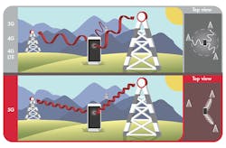
It’s expected that 5G will need to utilize higher-frequency spectrums in the millimeter-wave range when deploying active electronically scanned arrays (AESAs), which enables multi-beam multiplexing and massive multiple-input, multiple-output (MIMO) technologies (Fig. 1). Researchers working on the frontlines of forging this ultra-fast and high-bandwidth successor to 4G LTE are relying on modeling and simulation tools to optimize product development and test cycles.
Simulation supports designers throughout the design cycle by allowing them to virtually evaluate several design ideas and implement physical prototypes based on the most promising concepts. Another advantage lies in the possibility of investigating different boundary conditions. In this case, simulation allows an engineer to efficiently measure and test several scenarios—including extreme temperature variation, structural deformation, and chemical reactions—without damaging a prototype.
The goal of simulation specialists is to mimic the real world as closely as possible, so that the prototype is based on numerical results that achieve the expected performance in fewer design and test iterations.
Designers Join Forces with Simulation Specialists Through Apps
In preparation for the 5G rollout, designers are working through a number of obstacles, including frequency choices, propagation, reliability, battery life, and interference. Each of these challenges is represented by a unique blend of physics that require a simulation specialist in that specific area—one who is equipped with the right tools to set up the underlying mathematical model properly. The symbiosis between designers and simulation specialists needs to be perfect in order to deliver the right product at the right time.
Simulation experts are typically the only ones who can safely provide the input data needed to get a useful output from a model. They therefore have to be involved in the iteration process every time there is a new request or change to be made in the device being simulated. Additionally, results or outputs are often presented in an environment only familiar to the specialist, so distributing the information to their colleagues often requires a meeting to present an explanation and interpretation of the results.
But what if simulation specialists could easily build simulation apps (i.e., wrap an intuitive interactive user interface around a complex mathematical model)? What if users without any previous experience using simulation software could run apps specifically designed for them?
Simulation apps make it possible for simulation specialists to efficiently and effectively support the designers relentlessly working on the next breakthrough in the ultra-competitive landscape of wireless communication. Supplied with the right tools, designers working on 5G implementation can freely collaborate and complement their skills with those of their colleagues and collaborators who specialize in physics and numerical analysis.
What Simulation Apps Can Do for Wireless Communication Design
Let’s take the example of AESAs, or phase antenna arrays. They have become popular for military use in radar and satellite applications and are now occupying a conspicuous position for commercial purposes due to the growing needs of higher data rates in communication devices. The size of a simple component can easily exceed tens of wavelengths, making its numerical analysis very memory-intensive.
As a result, models take a very long time even when approximated values would be sufficient to evaluate a proof-of-concept design. Fast prototyping would help reveal performance tendencies and determine design parameters quickly.
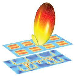
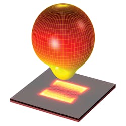
Fig. 2 shows a simulation of a 4-×-2 phased microstrip patch antenna array which can steer the beam toward the desired direction. This example is significantly more memory-intensive and will take a longer time to compute than a single microstrip patch antenna (Fig. 3). Simulation results shown in Fig. 3 are based on a full finite-element method (FEM) model of a single slot-coupled microstrip patch antenna built on low-temperature co-fired-ceramic (LTCC) layers, initially operating at 30 GHz.
Can we use the analysis of a single antenna to describe the behavior of the entire array? COMSOL Multiphysics software allows simulation specialists to perform an accurate simulation of a single microstrip patch antenna. They then take into account user inputs such as array size, arithmetic phase progression, and angular resolution to describe (for example) the 3D far-field of the entire array.
COMSOL makes it easy for specialists to couple physics interfaces already available with equations or algorithms needed to model a specific application. In this case, the two-dimensional antenna array factor has been implemented to include the translational phase shifts and array element weighting coefficients needed to determine the radiation pattern of the entire array.
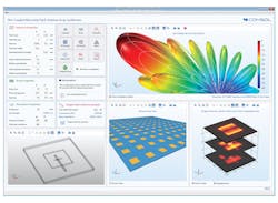
Can we present such a model to designers in a user friendly way? Simulation specialists are now provided with an intuitive workflow to create custom user interfaces based on their multiphysics simulation model. An app built for simulating the aforementioned antenna array is shown in Fig. 4.
This app allows the designer to change the physical size of the single microstrip patch antenna, the thickness and material properties of each layer, and any other relevant parameters determined by the simulation specialist. In this particular example, the simulation specialist has included an interactive user experience by indicating whether the chosen design parameters are appropriate or not by comparing the computed S-parameter (S11) value to the pass/fail target criterion.
This app also includes a results report and documentation that concisely explains how the app is working. This last feature can be used in a variety of practical ways, from building reports to stakeholders and management, to use as a training tool for new hires in the company. Apps can also be easily deployed to colleagues and collaborators through a local installation of the COMSOL Server product, which allows authorized users to access apps through COMSOL Client or a major web browser.
We have a lot of work ahead of us before 5G is unveiled to the public. When designers are equipped with the right set of tools, they can freely collaborate with colleagues throughout their organization and beyond. Working cross-departmentally will be key to competing and succeeding in the 5G race.
Jiyoun Munn, Technical Product Manager of RF

This file type includes high resolution graphics and schematics when applicable.
About the Author
Jiyoun Munn
Technical Product Manager, COMSOL Inc.
Jiyoun Munn is the technical product manager for the RF Module at COMSOL, and a senior member of IEEE. He has two decades of experience in the RF industry, developing over 150 antenna and microwave device prototypes. Munn also holds patents for antenna interrogation systems. He received his MS degree in electrical engineering from the University of Michigan.
