Analyzing Active Cancellation Stealth
This file type includes high resolution graphics and schematics when applicable.
Active cancellation stealth techniques have been in the planning phase for many years, and may now be put into practice with the availability of modern RF/microwave and digital electronics technologies. Military forces constantly seek tactical advantages; when properly implemented, active stealth methods can provide these. When developing cancelling waves and signals, errors in amplitude and phase must be minimized and various other factors must be considered to achieve true stealth performance.
The concept of active cancellation stealth has actually existed since the 1960s, with the basic idea being to produce a train of coherent waves that will reduce the scattering echo of a radar target, rendering the target “invisible” to a radar system. Active cancellation methods have several advantages compared to passive stealth techniques: They do not require changing the shape of a target, or spraying it, or coating it with absorbing materials.
They also can be used in many different frequency bands, as well as adjusted to the parameters of an incident radar wave signal. But active cancellation becomes more difficult with increasing frequency, making it appear most suitable for lower-frequency radar-cross-section-reduction (RCSR) applications, where passive stealth techniques have yielded poor results.1
Active cancellation stealth is believed to be a smart and adaptive technique that produces a artificial radiation field. Such a field has equal amplitudes and same-frequency, but opposite phase from the target’s scattering field. The enemy radar receiver is always located in the synthetic pattern zero, thereby suppressing the target echo signal received by enemy radar and ultimately achieving stealthy aim. The availability of modern microelectronics technologies is enabling more practical active cancellation stealth solutions.
According to the definition of RCS,2 it can be expressed as Eq. 1:

where:
(σ)0.5 = the complex root of the RCS scatterer;
λ = the wavelength;
k = 2π/λ = the wave number;
e$r = a unit vector aligned along the electric polarization of the receiver;
R = the distance between the radar and the scatterer;
Es = the vector of the scattered field; and
Ei = the electric field strength of the incident wave impinging on the target.
In theory, the RCS of a target (as it appears in different directions) can be measured accurately, as can the transient characteristics of a radar’s incident field. A radar system’s electromagnetic (EM) waves share characteristics with acoustic waves, and can be coherently stacked or cancelled in a similar way. In theory, achieving active cancellation is possible with a radar system by generating a wave with opposite phase.
According to ref. 3, any radar echo that satisfies the conditions described by Eq. 2 can be cancelled out completely:

where:
Δa = amplitude error;
Δf = frequency error; and
Δφ = phase error.
Unfortunately, a number of extraneous and often uncontrollable factors can yield errors when attempting to generate precise radar cancellation signals, defeating attempts at achieving active cancellation stealth effects. Minimizing these errors thus requires some analysis. Since waves reflecting from a complex target can be resolved into a collection of N discrete scatterers or scattering centers, Eq. 1 can be written in the form of Eq. 34:

where:
σn = the RCS of the nth scatterers and
φn = the relative phase of the scatterer’s contribution due to its physical location in space.
Many factors can impact the effectiveness of active cancellation efforts, with frequency error the most influential of these factors. Frequency errors can destroy signal coherent and cause a signal beat phenomenon, with loss of ideal cancellation effects. Even when the frequency difference is small and the signal is in pulse mode, new problems can arise. To simplify the radar cancellation model, the initial values of phase differences between two carriers can be set at odd times of π. The pulse train signal is represented by the sampling function:
∑nδn(t – nTt)
The synthesis of the field amplitude can be expressed by means of Eq. 4:

where:
Tt = the pulse repetition period;
a = Δf/Ωt;
Ωt = 2π/Tt, and E is given by Eq. 5:

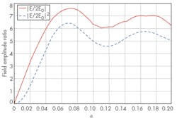
The coefficients of Eqs. 4 and 5 reach 0 at the same time if (and only if) variable a is an integer, which is when the stealth cancellation effect is at its best. When the number of pulse accumulations by the stealth system is large, such as 100, the cancellation effect is almost minimal. Figure 1 shows amplitude ratio versus parameter a (with a corresponding pulse accumulation number of 10).
As can be seen, cancellation effects are achieved only when the value of a is close to an integer. This frequency tolerance must be extremely tight in any active cancellation stealth approach.
This file type includes high resolution graphics and schematics when applicable.
Defining the System
This file type includes high resolution graphics and schematics when applicable.
In general, an active cancellation system can be divided into transmit and response waveforms according to the different methods of generating a cancellation wave. The transmit system must achieve consistent and accurate frequency, which may be possible through the application of digital-radio-frequency-memory (DRFM) technology.5-7
Considering the effects of phase errors, Eq. 6 can be derived from Eq. 3:

where:
σ = σ/σ0 = the normalized RCS;
σ0 = the original target RCS;
Δσ = σ1 – σ0 – (2k + 1)σ;
σ0 = the phase of the target; and
σ1 = the phase of the cancelling wave.
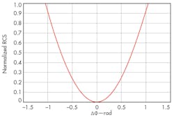
A plot of normalized RCS versus phase error is a parabolic curve (Fig. 2). From the chart, it can be seen that the phase error can’t exceed 60 deg.; the coherent wave can’t otherwise cancel the target echo, but may strengthen the scattering characteristics of the target. Since the curve is steep, it is indicating that the active cancellation stealth is very sensitive to phase error, and must be minimized in practice.
If only considering the effects of amplitude error, the following equation can be derived from Eqs. 2 and 3, resulting in Eq. 7:

where:
a = Δσ/σ0 and
Δσ = the amplitude error.
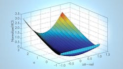
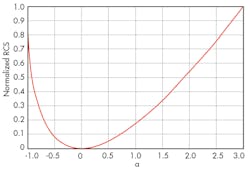
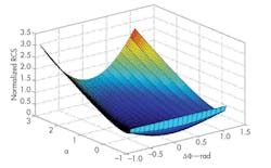
Figure 3 plots the relation between normalized RCS and the amplitude error. Since the curve has a gentle slope, it suggests that active cancellation stealth is not overly sensitive to amplitude errors. From Eq. 7, the scattering characteristics of target have not changed when a = -1 or a = 3, indicating little stealth effects from amplitude shifts. When a is greater than 3, the target echo is strengthened. Figure 4 shows that normalized RCS can change when phase and amplitude errors occur simultaneously. With only phase or amplitude errors, stealth conditions may not be severe. But when both errors occur simultaneously, achieving stealth conditions will be more difficult.
Some researchers have proposed an active cancellation system for special signals.8 The system must provide a number of functions, including real-time measurement of the signals of interest, precise target RCS, high-speed processing and transfer of data, cancellation and control of wave emissions, definition of stealth effects, and dealing with electromagnetic-compatibility (EMC) issues.
Measurements are more challenging since the modern radar reconnaissance environment has become more complex in terms of frequency range (which can extend beyond 0.05 to 100 GHz) and the number of pulses in the time domain (which can be millions per second). With the evolution of electronic hardware and software, modern signals and modulation formats become more complex, making measurements of these signals more difficult.
The growing use of digital-signal-processing (DSP) technology is radar receivers has helped to improve radar reconnaissance capabilities. In theory, DSP technology can treat signals in many different complicated EM environments, but in practice, may be subject to a number of bottlenecks. These include the limited processing speeds of broadband analog-to-digital converters (ADC) and supporting circuitry versus rapidly changing signal conditions for radar signals. Handling signals with complex modulation has been restricted by the use of ADCs with limited sampling rates and capabilities.
Some help may be available in the use of a broadband digital channel receiving and processing system realized through the use of a Fast Fourier Transform (FFT) algorithm that is based on the use of a field-programmable gate array (FPGA).9-13 This enables the stealth system to perform high-speed signal processing and real-time measurements.
This file type includes high resolution graphics and schematics when applicable.
The RCS Advantage
This file type includes high resolution graphics and schematics when applicable.
Determining the RCS of a radar target greatly impacts how effectively cancellation responses can be generated. The RCS of a target is based on complex physical parameters. Not only is it linked to the shape and physical properties of the target (such as the size, material, and structure), but it also has a close relationship with the incident EM waves (frequency, polarization mode, power, etc.). In addition, the sight angle between the target and the receiver can impact any RCS analysis. For example, the RCS characteristic of a large and complex shape aircraft can change one to two orders of magnitude in tenths of a degree of sight angle range. Its total dynamic range can be as high as 80 dB.
A target’s RCS can be determined by means of theory/analysis or by actual measurements. Theoretical approaches have been refined to accuracy with less than 3-dB error for many targets. Improving instruments, on the other hand, provides measurement accuracy in the range of 1 dB or less for errors. But three-dimensional RCS analysis and measurements can be quite complex, with fluctuating data that has made the development of radar stealth technology quite difficult.
Target RCS is not so much dependent upon only the radar wavelength as much as the polarization of the radar, and a large amount of data must be processed in any cancellation efforts. As an example, for a target RCS covered in the microwave region, if one band was intercepted (decomposed into 100 frequency points), information would be required to calculate as many as 500 data sets for analysis. If two polarization modes are considered, the amount of data would be doubled.
Data process requirements would increase further by considering the effects of azimuth angle (from 0 to 360 deg.) and elevation angle (from 0 to 180 deg.) on the computations. If the calculation interval is at 1 deg. and each RCS data segment consumes 4 B memory, the target RCS will require data storage approaching 494 MB. For processing increasing frequency ranges, the data requirements for stealth analysis increase dramatically.
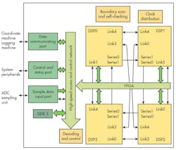
To meet the data requirements of real-time processing a parallel array architecture with a data pipeline is often used. For example, the FPGA + DSP + double-date-rate-3 (DDR3) architecture has been widely used for signal processing and data analysis in these demanding systems. In an example system (Fig. 5), DSP0 is the main processor and the other three DSPs serve as coprocessors. The system reconfiguration can be improved by using a mesh grid structure, where an FPGA is used as a coprocessor to complete the interface control and data communications for each DSP. Optical fiber communications is used to speed the data exchanges between modules.
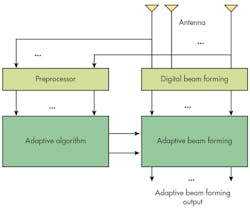
Active cancellation stealth technology depends on precise generation and control of cancellation waves. Previously, amplitude control of radar signals has been achieved by adjusting transmitter power. But with phased-array radar systems, adjustments in both amplitude and phase can impact radar signal amplitude levels. To ensure a system is capable of real-time performance, open-loop adaptive digital beam formation (DBF) must be used to minimize different kinds of interference across a large dynamic range. Its principle is shown in Fig. 6.
If the RCS of a target can be effectively reduced by cancellation of an EM field, then active cancellation stealth has been realized. But defining complete or partial stealth requires some index or threshold. As with cancellation, a definition of the stealth effect can be expressed by Eq. 8:

where:
Es = Asejφse$s
Ec = Acejφce$c
ΔEt = Atejφte$t
A = the amplitude; the subscripts s, c, and t = the target, cancellation field, and residual field, respectively; and e$ = the polarization mode.
Using decibels as units, the cancellation can be rewritten as Eq. 9:
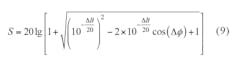
where:
Δφ = φs – φc with the units in radians and
ΔB = 20log(As) – 20 log(Ac).
When s = 0, complete stealth has been realized. The effect of stealth can also be characterized by the absolute or relative value of the least power density from the detected target versus clutter.
Active cancellation stealth technology is very sensitive to EM fields, and external fields can readily introduce interference errors. As a result, achieving EMC in any active cancellation stealth system design is essential, which requires understanding frequency- and time-domain characteristics and propagation characteristics of the active cancellation system. It also requires access to the latest EMI/EMC measurement equipment and analysis software.
In short, in analyzing the errors for any active stealth cancellation approaches, minimizing frequency errors is most critical, followed by minimizing phase errors (the admissible error angle is 60 deg.), and then amplitude errors. If all three types of errors exist simultaneously, they can greatly reduce the active cancellation stealth effects of the generated wave. The technologies needed to enable active stealth cancellation techniques are improving, but practical application of these technologies may still be somewhere in the future.
Xu Sheng, Engineering Doctorate
China Academy of Electric and Information Technology, Beijing 100041, People’s Republic of China; e-mail:
Xu Yuanming, Professor
School of Aeronautic Science and Engineering, Beihang University, Beijing 100191, People’s Republic of China
This file type includes high resolution graphics and schematics when applicable.
References
This file type includes high resolution graphics and schematics when applicable.
1. E.F. Knott, J.F. Shaeffer, and M.T. Tuley, Radar Cross Section. 2nd ed., SciTech Publishing, Inc. Raleigh, NC, 2004, p. 273
2. Merrill I. Skolnick, Radar Handbook, 2nd ed., McGraw-Hill, New York, 1990, Chaps.11.1-11.18.
3. Sheng Xu and Yuan-ming Xu, “Assemble an active cancellation stealth system,” Microwaves & RF, Vol. 51, No. 7, 2012, pp. S16-S22.
4. Wu Man-qing, “Development and Future Design of Digital Array Radar,” Radar Science and Technology, Vol. 6, No. 6, 2008, pp. 401-405.
5. J.M. Dunn-Rogers, “An analysis of the performance of DRFMS for EW systems,” IEE EW Colloquium, London, UK, 1991, sections 2/1-2/4.
6. Captain Scott, D. Berger and Lt. Col. David, E. Meer, “An expression for the frequency spectrum of a digital radio frequency memory signal,” IEEE National Aerospace and Electronics Conference, 1990, pp. 90-93.
7. S.J. Roome, “Digital radio frequency memory,” Electronics and Communication Engineering Journal, Vol. 2, No. 8, 1990, pp. 147-153.
8. Xu Sheng and Xu Yuanming, “Scheme for Nonlinear Frequency Modulated Signal Cancelling System,” Optik, Vol. 124, No. 21, 2013, pp. 4896-4900.
9. Zhu Jihan and Peter Sutton, FPGA Implementations of Neural Netsworks—A Survey of a Decade of Progress. Field Programmable Logic and Application, Springer, Berlin, Germany, 2003, pp. 1062-1066.
10. Eric Monmasson, “FPGA Design Methodology for Industrial Control Systems—A Review,” IEEE Transactions on Industrial Electronics, Vol. 54, No. 4, 2007, pp. 1824-1842.
11. Paul S. Zuchowski, Shelly G. Davis, and Brendan Cremen, et al., A hybrid ASIC and FPGA architecture. IEEE/ACM International Conference on Computer Aided Design, IEEE, New York, 2002, pp. 187-194.
12. Keith D. Underwood and K. Scott Hemmert, “Closing the gap: CPU and FPGA trends in sustainable floating-point BLAS performance,” Proceeding of the 12th Annual IEEE Symposium on Field-Programmable Custom Computing Machines (FCCM’04), IEEE, Albuquerque, NM, 2004, pp. 219-228.
13. Michael Ullmann, M. Huebner, B. Grimm, et al., “An FPGA run-time system for dynamical on-demand reconfiguration,” 18th International Parallel and Distributed Processing Symposium, IEEE, Berlin, Germany, 2004, pp. 1-7.
This file type includes high resolution graphics and schematics when applicable.
