Assessing Different Ultranarrowband Formats
Conventional modulation formats make use of upper and lower sidebands to send information with a carrier signal. Some formats use both sidebands, and are categorized as double-sideband (DSB) modulation, while some methods can transfer information by means of single-sideband (SSB) modulation. Ultrawideband (UWB) modulation spreads signals across a wide expanse of bandwidth, while ultranarrowband (UNB) modulation does not require the use of the sideband spectra. In an UNB communications system, all of the modulated information is in the lower sideband, while the upper sideband must be removed by means of filtering. UNB modulation can be an efficient means of transferring information, but requires the use of effective filters for optimum operation.
A great deal of suspicion has surrounded UNB modulation and whether it can truly delver the performance it promises with so little occupied bandwidth. UNB technology represents a general concept that includes a number of different modulation formats, including very-minimum-shift-keying (VMSK) modulation, pulse position phase reversal keying (3PSK) modulation, and very-minimum-chirp-keying (VMCK) modulation. Each approach offers advantages, along with the caveat that effective filtering is needed for each one. UNB communications systems differ from traditional communications systems which rely on sidebands as the means of transmitting modulated information, since the sidebands are not necessary for UNB communications.1 To better understand the potential uses for UNB modulation, different UNB formats will be compared, along with analyses of the filtering requirements.
The power spectral density (PSD) of an UNB modulation format as a function of frequency, GS(f), based a method in which the current bit is independent of the previous bit, can be given as Eq. 12:
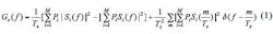
where:
M = the size of the symbol set;
Si(f) = the Fourier transform of the corresponding symbol
expression;
TS = the symbol period; and
Pi = the probability of occurrence for different symbols.
Frequency-domain plots for various modulation methods can be created by using Eq. 1. For realizing the values for pulse position phase reversal keying (3PRK) modulation, which is also known as missing cycle modulation (MCM), it is possible to apply Eq. 2 (although it is not given in ref. 3):
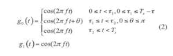
where:
g0(t) = the digital 0 and
g1(t) = the digital 1.
Only part of g0(t) is modulated. In this expression, TS is the bit period and τ= τ2 – τ1where τis the modulation duration time, with a value between 0 and T. Most of the time, τis equated to one carrier cycle time length, which is determined by the coding characteristics of the modulation format. Another higher-order modulation format, tristate integer cycle modulation (xMax), can be written in the form of Eq. 3:
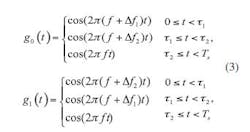
where g0(t) and g1(t) are used to represent digital zeros and ones, respectively. At the same time, a periodic wave can be inserted to control the sideband energy.4 In such a case, xMax modulation will have a similar coding method as 3PRK. Sinelike modulation is also similar to xMAX modulation.5
The symbol expressions for three-state pulse-step modulation (3PSM) can be defined by Eq. 4:
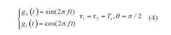
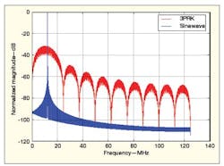
By taking the Fourier transform of these symbol expressions, and substituting the results into Eq. 1, the frequency-domain characteristics shown in Fig. 1 can be found.
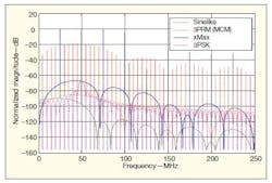
1. These plots show the power spectral densities (PSDs) for different ultranarrowband (UNB) modulation formats.
In using Eq. 1 this way, the different modulation formats can be compared. It is then possible to observe that all of the formats mentioned have wide continuous spectra and many line spectra. The 3PRK (MCM) format has the widest continuous spectrum and the closed line distribution. Because only one cycle is modulated, the continuous spectrum spreads quickly in accordance with the carrier frequency. The symbol period consists of 10 carrier cycles, so the data rate is relatively low. The line spectra is closely spaced on both sides of the carrier, spaced at one-tenth the carrier frequency.
Sinelike modulation also has a wide continuous spectrum. Its line spectra are spaced according to the data rate: One symbol consists of two half cycles with slightly different frequency, with one frequency somewhat higher than one-half the carrier frequency and the other somewhat lower than one-half the carrier frequency. The whole symbol period is equal to two times the carrier period, so the data rate is equal to one-half the carrier frequency. The spacing among the line spectra is much greater than that of 3PRK (MCM) modulation—about five times greater, as shown in Fig. 1.
For xMax, two carrier cycles are modulated for 1 b, so the data rate is still one-half the carrier frequency. The main difference between xMax and sinelike modulation is that 1 b consists of two complete sinewave cycles with slightly different frequency. For its symmetric modulation, 3PSK does not have sideband line spectra, verifying the conclusion made in ref. 1: Sideband spectra are not required for UNB modulation.
Many of these modulation formats have common traits: line spectra that are equally spaced on both sides of the carrier according to the data rates, a strong carrier, and a low wide sideband. All of the required phase modulation information can be found in the lower sideband.1
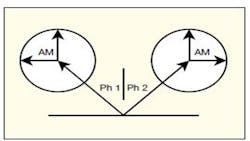
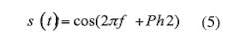
As detailed in ref. 3, filtering is essential to any implementation of UNB modulation, notably a zero-group-delay filter (ZGDF) or a negative-group-delay filter (NGDF). The ZGDF is generally emphasized in most reports, so that the high-speed modulation information can be preserved after filtering. Because a conventional filter exhibits large group delay or rise time when the bandwidth of the filter is narrow, the large group delay will remove any high-speed modulation information. In order to realize UNB communications, special filters are required. A prototype of a ZGDF is shown in Fig. 2. This high-quality-factor (high-Q) crystal filter has an ultranarrow bandwidth, which can filter out most of the noise. At the same time, the filter has a large Nyquist bandwidth; electrically, the crystal resonator appears as a pure resistance. As Fig. 3, the crystal resonator also provides a reference signal with phase, which can be expressed as Eq. 5. Using the vector summing shown in Fig. 3, it is possible to analyze the behavior of the ZGDF for the purpose of designing such a filter for an UNB communications system.
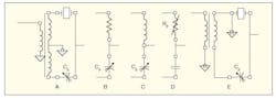
2. This five diagrams show the circuit details for a zero-group-delay filter (ZGDF)
needed to achieve UNB communications.
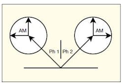
3. This simple diagram demonstrates the phase summing that occurs within a ZGDF.
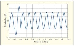
4. This waveform shows the effects of vector summing when phase 1 and phase 2 of π/3.
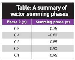
In processing UNB signals with a ZGDF, a received signal has phase 1, with some amplitude modulation, while the reference with phase 2 also has some amplitude modulation. When a received signal has a phase 1 equal to π, and the reference has a phase 2 of π/3, the summed result is shown in Fig. 4 as −0.1677π. There is some loss of phase in the process, along with some amplitude modulation (Fig. 3). The table shows the values for when the reference signal has a different phase 2. When phase 2 is 0.1π, the summing phase is at its largest value, with a corresponding waveform shown in Fig. 5 and a numerical description presented in Eq. 5:
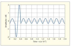
5. The effects of vector summing are shown here for phase 1 of π and phase 2 of 0.1π.
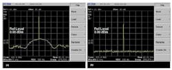
Sideband line spectra are not required for UNB. But to satisfy the Nyquist bandwidth requirements, a lower continuous spectrum is required to contain or represent the modulation information. This is also given and analyzed in ref. 1. Figure 6 offers a comparison of various modulation formats, where the line spectra have been removed and only the carrier and the lower sideband remain. A pure sinewave signal is included for comparison, with the only difference between it and the other modulation formats being its continuous spectrum. This further verifies that the lower continuous sideband spectrum contains the modulation information, which is only phase modulation, since all sinx/x amplitude modulation has been filtered out.1,3 Figure 7 provides spectrum-analyzer screen shots with measured results at 400 MHz for a sinewave signal (b) in comparison with an UNB signal (a).
6. These plots of normalized magnitude compare the PSDs for a sinewave and for 3PRK modulation.
When coding formats are different, the continuous spectral widths of the modulation formats are also different. Although these spectra may be at low levels—even embedded in the system noise level—it is necessary to compress the spectral widths to conserve spectrum. A method for accomplishing this is provided in Eq. 3, with the spectral characteristics resulting from the operation shown in Fig. 8. The demodulation performance is presented in Fig. 9.
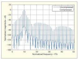
8. These traces compare the normalized magnitudes (PSDs) of signals with compressed and uncompressed sidebands.
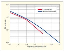
9. These plots show BER performance levels as a function of signal-to-noise ratio (SNR) for signals with compressed and uncompressed sidebands.
As the dotted line in Fig. 8 shows, the continuous bandwidth is gently compressed by the process of applying Eq. 3. In these studies, the carrier frequency is 10 times the data rate, and the bandwidth reaches 0.5 b/s/Hz. If the sideband power is considered for the compressed spectrum, the bandwidth then becomes 0.5 b/s/Hz − 60 dB. If the bandwidth efficiency is calculated according to the ultranarrow line spectrum shown in Fig. 7(a), it is very high. After compression, the BER improves as the signal-to-noise ratio (SNR) increases.
In conclusion, the frequency-spectrum and modulation characteristics of various UNB modulation formats have been examined, and the principle of the ZGDF needed for these formats has been investigated. From these studies, it can be seen that the sideband spectra, which represent the sinx/x modulation, are not needed for an UNB system. In any UNB format, all the modulation information is contained within the lower continuous spectrum. This continuous spectrum must be compressed, which can effectively conserve available spectrum while still achieving high data rates.
Acknowledgment
This work is supported by the National Natural Science Foundation of China (NSFC) under Grant No. 61001102.
References
1. H.R. Walker, "Sidebands Are Not Necessary," Microwaves & RF online, www.mwrf.com/systems/sidebands-are-not-necessary.
2. Mischa Schwartz, Information Transmission, Modulation and Noise, McGraw-Hill, New York, 1951.
3. H.R. Walker, Ultra Narrow Band Modulation Textbook, 2011, available from http://www.vmsk.org/.
4.Stuart Schwartz, Overview and Evaluation of xMax. http://www.xgtechnology.com/, technical_documents.asp, 2007-6.
5. K.H. Sayhood and Wu Lenan, "Raise Bandwidth Efficiency with Sinewave Modulation VMSK," Microwaves & RF, April 2001, pp. 79-84.
6. Shikai Zhang, "UNB Modulation Salvages Spectrum," Microwaves & RF, April, 2009, pp. 55-63.
