Design Improves 4.3-GHz Radio Altimeter Accuracy
This file type includes high resolution graphics and schematics when applicable.
Short-range radio altimeters are important safety and navigational tools in small aircraft. Usually designed as short-range frequency-modulated (FM) radars in the 4.2-to-4.4-GHz band,1 their main applications are for instrument-based approaches and landings for larger commercial aircraft, although they are also suitable for smaller aircraft and even unmanned air vehicles (UAVs). The accuracy and resolution of aviation altimeters is usually limited to a few feet due to the limited availability of bandwidth (200 MHz) in the 4.3-GHz range. Fortunately, by adding a second receiver channel in quadrature, it may be possible to dramatically improve the resolution and accuracy of these short-range radio altimeters.
The basic operation of a radio altimeter is shown in Fig. 1. It is a low-power, continuous-wave (CW) radar system that generally requires separate transmit and receiver antennas. The radio-wave propagation delay is usually too short to switch a single antenna between the transmitter and the receiver. Most attempts were directed toward improving the radio-altimeter reliability involving parallel operation of two or three instruments on the same aircraft. Most aviation radio altimeters have separate transmit and receive antennas although considerable efforts were invested into developing a single-antenna radio altimeter.2
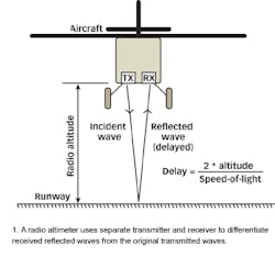
For correct operation, the receiving antenna should detect only the reflected signal from the runway and not the radio signal coming directly from the transmitting antenna. The two antennas must be widely separate to avoid crosstalk. Although electronic filtering of the crosstalk allows the design of single-antenna radio altimeters, the operation of the latter is usually limited above a specified minimum altitude.
Most aviation radio altimeters are frequency-modulated (FM) CW radars. The carrier frequency of the transmitter is swept continuously in a given frequency range. Since the received signal is delayed, the receive frequency differs from the transmitter. If the rate-of-change of the transmitter frequency is constant, the delay and therefore altitude are directly proportional to the measured frequency difference between the transmitter and receiver.
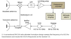
Figure 2 shows the design of a conventional FM radio altimeter. The sweep waveform is triangular and both slopes are typically used for the altitude measurement to compensate for the Doppler shift due to the vertical speed of the aircraft. The sweep frequency is usually between 50 and 300 Hz. The higher limit is imposed by the receiver thermal noise, the lower limit is the ability of the radio altimeter to eliminate the Doppler shift in the case of a descending or climbing aircraft.
Most aviation radio altimeters operate in the 4.2-to-4.4-GHz frequency band. Of the 200 MHz available, only about 150 MHz in midband is typically used. The 4.3-GHz (7-cm-wavelength) frequency band is a compromise between the bandwidth available (accuracy of the measurement) and the surface roughness of the runway or other reflecting target. Transmitter power ranges from 10 mW (+10 dBm) to 500 mW (+27 dBm). The directivity of both transmit and receive antennas is limited to about 10 dBi to allow the operation of the radio altimeter at moderate pitch and bank angles of the aircraft.
The receiver is a homodyne design using a mixer to derive the difference between the transmit and receive frequencies. The beat frequency is usually less than 1 MHz. Part of the transmitter signal is also used as the local oscillator (LO) for the receiver. Some radio-altimeter designs may simply use the crosstalk between the transmit and receive antennas to feed the LO signal in the receive mixer.
The beat signal is filtered first, then amplified and limited. A frequency counter drives the altitude indicator and various altitude alarms if required. Of course, transmission delays (due mainly to the cables connecting the antennas to the electronics of the radio altimeter) must be subtracted from the measured altitude.
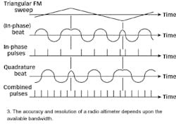
Figure 3 shows that the accuracy and resolution of a radio altimeter are limited by the RF bandwidth. For a given frequency sweep, the electronics produces a certain beat frequency with a limited number of transitions that can be counted. As the measured altitude changes, the beat pattern shifts and the counter result actually makes several oscillations between two adjacent values.
There are different ways to improve the accuracy and resolution of a radio altimeter. The simplest solution is to increase the frequency sweep up to 400 MHz as suggested in ref. 3. A better solution is to add a low-frequency (around 10-Hz) triangular dither waveform to the main triangular sweep. In this way the oscillations between two adjacent values are averaged out during several measurements, however some additional bandwidth is required for the dither.
The approach in this article is to add a second receiving channel in quadrature. In this way the number of available transitions is doubled and the accuracy and resolution are improved by a factor of 2. Further, the low-frequency dither amplitude can be halved so that less bandwidth is wasted for the dither. Finally, a quadrature design of a homodyne receiver is required anyway to extract all of the available information out of the received signal.
To demonstrate the author's approach, an accurate radio altimeter with a dual-channel (quadrature) homodyne receiver was developed and built (Fig. 4). The main application of this radio altimeter is to aid in small aircraft landings. The transmitter modulator includes two triangular oscillators: the main sweep at 150 Hz and the dither at 15 Hz. The dither amplitude is set to about 10 percent of the main sweep amplitude. The sum of both waveforms is applied to the microwave voltage-controlled oscillator (VCO) operating directly at 4.3 GHz. The VCO includes a BFP420 transistor amplifier from Infineon Technologies (San Jose, CA) and an interdigital filter in the feedback. Due to the relatively narrow sweep, only the central microstrip resonator is tuned with a single BBY51 varactor diode from Infineon.4
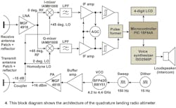
The VCO is followed by two amplifier-buffer stages using another BFP420 bipolar transistor and a MGF4918 high-electron-mobility transistor (HEMT) from Mitsubishi Electronics America (Sunnyvale, CA). The latter produces RF power of about 40 mW (+16 dBm) at 4.3 GHz. Most of this signal is fed to the transmit antenna, while a small fraction (about 1 mW or 0 dBm) is coupled and sent through a lowpass filter to provide the homodyne LO.
The receiver RF front end includes a single-stage low-noise amplifier (LNA) with another MGF4918 HEMT and two IAM81008 balanced mixers from Agilent Technologies (Santa Clara, CA) in quadrature. The RF and LO signals are split with two Wilkinson hybrids. Different-length microstrip lines are used to obtain the required phase shifts. The IAM81008 mixers (formerly from Avantek and now obsolete) are used beyond their designed frequency range in this application, therefore the overall noise figure of the receiver is in the 15-to-20-dB range.
The RF section of the radio altimeter is built on two (transmitter and receiver) printed-circuit boards (PCBs) fabricated in microstrip technology (Fig. 5).
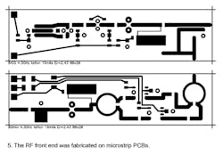
Each PCB is 80 mm long and 20 mm wide. Both boards are etched on 19-mil-thick Ultralam 2000 teflon laminate from Rogers Corp. (Rogers, CT) with a dielectric constant of 2.43. Figure 6 shows the top side of both boards; the bottom side is not etched to act as the microstrip groundplane. Both boards are soldered in a frame made of thin brass sheet for shielding purposes.
Both in-phase (I) and quadrature (Q) beat signals are filtered and amplified. The dual-channel amplifier has a common automatic-gain-control (AGC) circuit. The AGC time constant must be carefully chosen to minimize the effects of signal dropouts due to poor reflections. Noise is removed by two Schmitt-trigger stages driving a pulse-former circuit that produces one output pulse for every zero crossing of any of the two input signals.
The pulses are fed to a frequency counter implemented inside a 8-b PIC16F84A microcontroller from Microchip Technology (Chandler, AZ). The gate of the counter is not synchronized to the main sweep nor to the triangular dither. The microprocessor however performs digital averaging (filtering) of the measured result. Due to the relatively low frequencies involved, a clock frequency of only 4 MHz is more than sufficient for the PIC16F84.
Radio-altimeters
The result of the measurement is displayed on a four-digit liquid-crystal-display (LCD) screen: hundreds, tens, and units of feet and one decimal indicating one-quarter-ft. increments. The microprocessor also removes unnecessary information from the LCD: the decimal is blanked above 10 ft. and both the units and decimal are blanked above 100 ft. The PIC16F84's internal electronically erasable programmable read-only memory (EEPROM) stores the offset of the aircraft-installation delay that has to be subtracted from the measured result.
A numerical display is of limited use during the quick and critical flare of a small aircraft. Therefore, the radio altimeter is equipped with a voice synthesizer built around the ISD2560P voice-recorder chip (analog EEPORM storage) from Winbond Electronics Corp. America (San Jose, CA). The ISD2560P contains 21 prerecorded voice messages actually using less than one-half of the chip's total storage area. The actual message telling the current altitude in feet is selected by the PIC16F84 and played back by the ISD2560P through a loudspeaker or through the aircraft's intercom system.
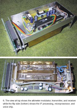
The electronics package of the radio-altimeter prototype is 140-mm long, 66-mm wide and 42-mm high (Fig. 6). The package cross-section is mainly defined by the size of the front-panel LCD. The modulator, transmitter, and receiver RF stages are located on the bottom side in Fig. 6 (bottom). SMA rather than TNC connectors are used for both antennas to keep the weight and size as small as possible.
The dual-channel intermediate-frequency (IF) signal amplification and processing, microprocessor, and voice synthesizer are located on the top side in Fig. 6 (previous page). Since both the PIC16F84 and ISD2560P had to be reprogrammed several times during the experiments, dual-in-line-packaged (DIP) versions of both chips were installed in sockets in the prototype. Of course, most of the remaining components are surface-mount devices (SMDs) placed on the copper side of the single-sided PCBs.
The offset to compensate for the aircraft-installation delay is set by a single pushbutton on the rear panel. A quick depression of this pushbutton just shows the value stored in the EEPROM on the LCD. A long depression (more than 6 s) actually writes the new value into the EEPROM, setting the display to zero. This operation is therefore conveniently performed on ground before the actual flight.
Radio altimeters are usually installed on large aircraft with fuselages made from conducting materials like aluminum or carbon-fiber composites. In such a case, it is relatively easy to obtain a good isolation between the transmit and receive antennas. Further, the results are quite predictable regardless of the actual type of aircraft. Unfortunately, many small aircraft have nonconducting fuselages made of fabric, wood, or glass-fiber-epoxy. Additionally, wood and glass-fiber composites are part of the structure of small aircraft, therefore large holes for radio-altimeter antennas can not be cut in the fuselage without compromising the structural strength of the aircraft. On the other hand, internal antennas are a viable solution on aircraft with transparent fuselages for microwave transmission and reception.
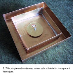
Figure 7 shows an effective internal radio-altimeter antenna design. The antenna includes a linearly-polarized patch with air dielectric installed inside a cavity. Choosing the correct size of the cavity significantly decreases the unwanted coupling between the two radio-altimeter antennas. A quarter-wavelength choke around the cavity further decreases the coupling. The cavity and choke walls also act as a practical spacer when the antenna is placed on the glass-fiber-composite floor of the fuselage. This antenna is relatively simple to manufacture from thin brass sheet. It achieves more than 11-dBi gain and about 15 dB impedance matching across the full 4.2-to-4.4-GHz radio-altimeter band. Of course, the antenna must be tuned to the actual glass-fiber fuselage thickness.
The prototype radio altimeter prototype, including antennas, was installed on a motorglider aircraft and tested in several hundred landings on different runways and in different weather conditions (different soil moisture) over two years. Of course, the performance of any radio altimeter depends heavily on the soil reflectivity and roughness. The prototype was found to operate to about 1000 ft. over average (grass) surfaces. The range is much higher on well-reflecting surfaces like still water while it may drop to 500 ft. under unfavorable conditions (trees). The range of this design is mainly limited by the relatively high noise figure of the receiver and low transmitter power. Both could be improved using better components. Since this radio altimeter was mainly intended as a landing aid operating during the final approach and flare of a small aircraft, a range of 500 ft. was considered sufficient.
The accuracy of the radio altimeter mainly depends on the reflecting target. Reproducible results were always obtained over smooth, paved (concrete) runways. Over grass runways the result of the measurement typically deviates by ±0.5 ft. This means that dithering is not strictly necessary over grass runways, since the changes of the grass reflectivity produce a similar averaging. Without dithering the counter increments are around one foot in a quadrature design in the standard 4.2-to-4.4-GHz band. Unfortunately, on some rare occasions the reflectivity of grass runways was found so low that the radio altimeter could not provide any meaningful results.
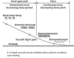
Since a digital altitude display was difficult to read and therefore of limited use during challenging landings, a simple acoustic interface (Fig. 8) was tested during the experiments with good success. The radio altimeter is switched on at the beginning of the final approach, when the acoustic signal is an intermittent tone of constant pitch and variable period. As the aircraft descends down to the runway, the beep period increases. At the beginning of the flare, the beep period increases to infinity, the sound therefore becomes a continuous tone. The altitude information is thereafter relayed by the decreasing tone pitch. The tone pitch decreases down to zero when the landing gear touches the runway.
Although the acoustic interface was found to be quick and reliable, supporting the final approach and flare in the most critical configuration of the aircraft with the flaps and/or spoilers fully deployed, it required additional training for the pilot. An additional disadvantage is that the simple acoustic signal can easily be confused with beeps originating in other instruments on-board an aircraft. As a result, it was necessary to develop a simple-to-understand voice synthesizer. It was found sufficient to describe the altitude of the aircraft in feet with 21 different words: minus, zero, half, one, two, three, four, five, seven, ten, fifteen, twenty, thirty, fifty, seventy, one-hundred, one-hundred-fifty, two-hundred, three-hundred, four-hundred, and five-hundred. The resolution was intentionally made coarse at higher altitudes to avoid overloading the pilot with unnecessary information.
The success of the prototype radio altimeter demonstrates that an effective design can be implemented with low-cost electronic devices. The design could be improved with a better RF front end to improve the range and reliability over poorly reflecting surfaces. In addition, a digital signal processor (DSP) could be used to remove crosstalk between the two antennas. Finally, if both quadrature beat signals are fed to a signal processor to measure the phase, the dithering becomes unnecessary.
ACKNOWLEDGMENT
This research was supported by the Ministry of Higher Education, Science, and Technology of Republic Slovenia under the research program P2-0246.
REFERENCES
- Werner Mansfeld, "Funkortungs- und Funknavigationsanlagen," 1994 Hüthig Buch Verlag GmbH, Heidelberg, ISBN 3-7785-2202-7, pages 337-342.
- Leo G. Maloratsky, "An Aircraft Single-antenna FM Radio Altimeter," Microwave Journal, May 2003, ISSN 0192-6225.
- Giorgos E. Stratakos, Paul Bougas, and Kostas Gotsis, "A Low Cost, High Accuracy Radar Altimeter," Microwave Journal, February 2000, ISSN 0192-6225.
- Matjaz Vidmar, "A Wideband, Varactor-tuned Microstrip VCO," Microwave Journal, June 1999, ISSN 0192-6225.
