This file type includes high resolution graphics and schematics when applicable.
Software may be what defines the functionality of a software-defined radio (SDR), but hardware is still a critical part of the radio—whether it is in a smart cellular phone or a tactical radio for military use. The software can only achieve the performance levels made possible by the essential hardware components within the radio, including analog-to-digital converters (ADCs), digital-to-analog converters (DACs), field-programmable gate arrays (FPGAs), and integrated-circuit (IC) radios.
In its simplest form, an SDR feeds incoming signals from an antenna to an ADC to be digitized and passed along to a digital baseband processor. For the transmit function, data from the baseband processor is passed to the DAC and converted to analog voltages for transmission over the same antenna. But digital and mixed-signal components can only carry part of the lead in an SDR design. Additional analog components (such as amplifiers, filters, and limiters) are needed to achieve an acceptable dynamic range for real-world signals, which they achieve by generating high-enough input levels to the ADC and output levels from the DAC.
A continuing trend in the design and development of radio ICs for SDR applications is to include as many component functions as practical within a single IC, housed within a single multipin package. Such functions include analog upconversion and downconversion of frequencies, by means of frequency mixers and local oscillators (LOs). The integration within a single IC simplifies the circuit-level SDR block diagram while shrinking the size of the radio hardware. Whether in discrete or integrated forms, these component functions are critical for SDR performance. As the data converters, FPGAs, and other components improve in performance, they enable improved performance from final SDR circuit boards and products.
As the model AD9361 transceiver IC from Analog Devices demonstrates, direct-conversion techniques help to simplify the amount of RF/microwave circuitry added to the data converters in a radio IC for SDR use, while also supporting wide bandwidths. Nominally developed for cellular-radio base stations, this device operates from 70 MHz to 6.0 GHz with channel bandwidths from 200 kHz to 56 MHz for flexibility. The radio’s RF/microwave front end works with a mixed-signal baseband processor to enable a straightforward interface to a programmable digital processor.
The device actually contains two independent direct-conversion receivers with on-board LOs and phase-locked loops (PLLs) for processing digital modulation formats based on in-phase (I) and quadrature (Q) signal components. By changing sample rate, digital filters, and decimation, the radio IC can change channel bandwidths according to software programming. While not a complete SDR system on a chip (SoC) device, it is a flexible integrated starting point for SDR circuit-level designers, given the wide bandwidths and modulation versatility. The AD9361 is supplied in a 144-ball chip-scale package (CSP) measuring 10 × 10 mm.
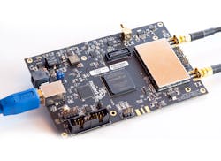
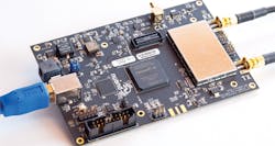
For those who would prefer to get a head start on the SDR design process, Analog Devices also offers its model AD-FMCOMMS3-EBZ demonstration module and reference design, based on the AD9361 transceiver IC (Fig. 1). The module allows designers to quickly measure waveforms from the IC based on programming code, the better to understand the relationship of hardware and software in an SDR.
The AD-FMCOMMS3-EBZ module is also available as part of the ZedBoard SDR design kit from Avnet, which additionally incorporates the programmable Zynq-7020 SoC with integral FPGA from Xilinx. The Zynq-7020 might be described as the combination of a microprocessor and an FPGA, providing two essential SDR functions in one packaged IC, in keeping with a trend of increasing integration of components for SDRs.
The ZedBoard SDR circuitry can be programmed by means of Vivado design software from Xilinx or by using software from one of the firm’s SDR reference designs; at least one of these adapts Long-Term-Evolution (LTE) standards for public-safety radios. Software for the SDR radio kit can run on numerous operating systems, including Mac OS, Windows, and Linux.
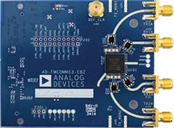
Texas Instruments also offers an SDR design kit, its TIDEPOO40 SDR reference design (Fig. 2). Incorporating the firm’s OMAP-L138 dual-core microprocessor and a Spartan 6 FPGA from Xilinx, this SDR hardware/software reference design includes source design files and a complete bill of materials (BOM) for rapid entry in the development of an SDR. The reference design is based on the MityDSP-L138F system on module (SOM) from Critical Link LLC and includes ARM-based graphical-user-interface (GUI) software, along with sample microprocessor software to help speed the SDR development process.
Building a Radio
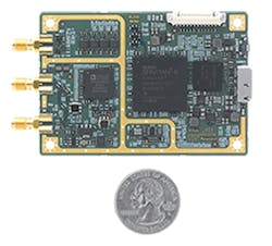
Commercial SDR designers often employ a practical blend of ICs and discrete components, enabling them to choose component function blocks (such as FPGAs and microprocessors) with the best possible performance for their particular set of design goals. Commercial board-level SDRs like the Universal Software Radio Peripheral (USRP) B200mini Series of business-card-sized radios from Ettus Research, a National Instruments Co., provide a good example of how available mixed-signal and digital IC components can be combined for outstanding SDR performance.
The compact board (Fig. 3) incorporates a model AD9364 transceiver IC from Analog Devices for front-end functions, with a Spartan-6 FPGA from Xilinx for programmability. The AD9364 matches the 70-MHz-to-6-GHz total frequency range and bandwidths of the AD9361 radio IC, with one on-chip direct-conversion receiver rather than the two receivers in the AD9361. The miniature SDR, with instantaneous bandwidth of 56 MHz, draws power from a high-speed Universal-Serial-Bus (USB 3.0) connection for streaming data to a host computer. It is meant as a building block for larger radio designs and can be synchronized with a standard 10-MHz clock reference source or pulse-per-second (PPS) time reference signal.
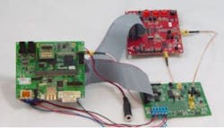
Another design example for SDR experimenters is the bladeRF transmit/receive board (Fig. 4) from Nuand, with a frequency range of 300 MHz to 3.8 GHz. The SDR module measures 5.0 × 3.5 in. with gold-plated SMA connectors. It performs independent receive/transmit sampling with the aid of a 12-b, 40-MSamples/s ADC and 16-b DAC. It also includes a general-purpose microprocessor with on-board memory as well as an FPGA from Altera or flexible programming.
The board can be configured for 2 × 2 multiple-input, multiple-output (MIMO) antenna systems and expanded for 4 × 4 MIMO systems. The SDR board is also capable of operating as a spectrum analyzer, vector signal analyzer, and vector signal generator. It features support for Windows, Mac OS, and Linux operating system software and is powered by a host computer via USB 3.0 port.
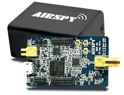
For those only concerned with SDR receive functions, the Airspy One series of SDR receivers (Fig. 5) from Airspy provide continuous coverage from 24 to 1,800 MHz with 10-MHz instantaneous bandwidth, including the use of tracking RF filters to reduce noise levels. It incorporates 12-b analog to digital conversion at 20 MSamples/s. It can be synchronized with external (GPS) signals or a rubidium reference clock (10 to 100 MHz) to achieve high stability.
Developing control software for an SDR is obviously as important as finding the optimum blend of hardware, and software simulation tools such as MATLAB and SIMULINK from The MathWorks can provide modeling tools for determining the parameters to program an SDR’s digital components, such as its FPGAs. Software is developed according to the Software Communications Architecture (SCA) standard derived from the early work of the U.S. military’s Joint Tactical Radio System (JTRS) efforts to develop a universal radio platform for all of its branches. In addition, middleware such as Common Object Request Broker Architecture (CORBA) works as part of the SCA code to facilitate interaction of SDR software modules from different sources.
One challenge facing all component developers for SDRs lies in meeting higher performance goals with lower power consumption—whether for commercial, industrial, or military markets—since the majority of SDRs will be powered by batteries, and power-hungry components can drain a radio’s battery quickly. Solutions continue to be found by means of dense circuitry within compact ICs, fabricated with semiconductor processes capable of ever-smaller feature sizes.
SDR technology is certainly no longer novel, and many of the semiconductor component suppliers addressing this market are making great strides in providing higher-performance, lower-power devices to meet next-generation SDR requirements.
Looking for parts? Go to SourceESB.
This file type includes high resolution graphics and schematics when applicable.
About the Author
Jack Browne
Technical Contributor
Jack Browne, Technical Contributor, has worked in technical publishing for over 30 years. He managed the content and production of three technical journals while at the American Institute of Physics, including Medical Physics and the Journal of Vacuum Science & Technology. He has been a Publisher and Editor for Penton Media, started the firm’s Wireless Symposium & Exhibition trade show in 1993, and currently serves as Technical Contributor for that company's Microwaves & RF magazine. Browne, who holds a BS in Mathematics from City College of New York and BA degrees in English and Philosophy from Fordham University, is a member of the IEEE.
