This file type includes high resolution graphics and schematics.
High-frequency measurement systems based on vector network analyzers (VNAs) are available for analyzing the performance of multiport active and passive components well through millimeter-wave frequencies. But their high resolution and broad frequency ranges mean very little if these systems are not accurate, and that requires proper calibration practices. Fortunately, automatic calibration methods can help maintain the accuracy of VNA-based systems without the cost of excessive test-system downtime or lost production measurement throughput.
Related Articles
• Vector Network Analyzers Support Versatile Testing
• Balanced Amplifier Aims For Low Noise
• VNA Modules Aid Antenna Testing
Four-port RF/microwave VNAs are available from numerous test-equipment suppliers in various configurations, delivering superb performance in terms of scattering (S) parameters, amplitude, and phase for active devices; active and passive components; and even integrated subassemblies. They can also provide high accuracy, but that accuracy relies on proper calibration of the test system. A typical VNA-based automatic-test-equipment (ATE) system includes test cables and switches that add some loss, group delay, and dispersion that must be removed from the final measurement results displayed for a multiport device under test (DUT). A proper calibration should remove the electrical contributions of these additional components and modules that are necessary parts of the test signal path.
To maintain test-system accuracy, a calibration should be performed each day, with the test system calibrated at the DUT ports. Unfortunately, manual calibration procedures are very time-consuming and prone to errors. In addition, the time required for a manual calibration means less time for the test system to evaluate DUTs that may be running through final test procedures prior to shipment to a customer. The time required for calibration takes away from the system throughput and must be minimized to reduce the cost per tested unit.
Of course, without a calibration, or with a poorly performed calibration, a test system will yield poor measurement accuracy, and this can be devastating to a company in many ways. When a VNA-based test system is not properly calibrated, and the accuracy is low, the measurement uncertainty can result in DUTs that do not meet specification being approved for final shipment, as well as some DUTs that actually meet their minimal specification limits being failed because of the poor measurement accuracy. Both cases can be costly to a manufacturer. Shipping parts that do not meet required performance specifications will result in failures for a customer’s end products that incorporate those DUTs, and the resulting difficulties in customer relations because of those failures. Also, discarding parts that might have exceeded those minimum performance requirements results in increased material costs.
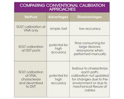
Perhaps the most popular VNA calibration approach is the short-open-load-through (SOLT) method, which is typically used for a two-port instrument calibration and relies on measurements of well-defined passive circuit standards to establish the accuracy of the test system across its operating frequency range. As part of the SOLT calibration process, the measured characteristics (including amplitude and phase response and S-parameters) of each reference standard are compared to the known values of those parameters for the standard. As noted, however, it can be extremely time-consuming to perform, with the need to switch among the four standards, and it can be prone to mistakes that lead to measurement/calibration errors (see table).
Commercial calibration kits with the physical standards are available from a number of suppliers, or else standards can be constructed based on known electrical/mechanical parameters—such as the electrical length of a transmission line at a given center frequency. Once the reference standards are measured, an RF/microwave VNA compares the measured values with the known values for each standard, and computes a correction factor for each measured frequency point based on well-defined calibration equations. These correction factors are then applied during subsequent VNA measurements.
The measurement or reference plane is defined by the physical location where the calibration standards have been connected to the system, and this is also the point at which the correction factors are applied to begin a measurement. If coaxial cables were used during the calibration, with the cables connecting the reference standard to the VNA, then the reference plane is at the end of the coaxial cables.
This file type includes high resolution graphics and schematics.
A Better Way
This file type includes high resolution graphics and schematics.
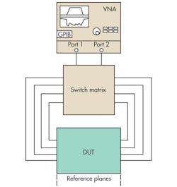
In contrast to manual calibration methods, an automated calibration approach developed by ATE Systems provides the means for calibrating a VNA-based measurement system at two or more ports and across 2000 test points at an intermediate-frequency (IF) bandwidth of 3 kHz. This automated calibration approach (Fig. 1) makes possible an in situ calibration of a VNA-based ATE system, without removing a DUT or the calibration standards. It eliminates the errors that can result from manual calibration methods, and can provide the levels of accuracy possible with through-reflect-line (TRL) calibration approaches.

1. This block diagram shows how the automatic calibration solution is connected to a VNA-based test system and enables a reference plane to be established at the DUT without constantly changing calibration standards.
This in situ calibration process also removes any inaccuracies resulting from test cables shifting position due to flexure. The automated calibration process requires very little time, allowing it to be performed more frequently (on a daily basis or as needed). The speed of the calibration approach increases the availability of the test system for production-line measurements and reduces the effective cost per DUT test.
The automated calibration solution supports measurements on devices and components with two or more ports—it can be configured for four or more ports depending upon a DUT, and the measurement reference planes can be established right at the DUT. It works with systems based on commercial VNAs and includes an instrument correction module (ICM) that mounts directly onto the front panel of the analyzer and one or more fixture characterization modules (FCMs) for connection to a DUT. FCMs are connected to an FCM controller which coordinates switching and multiplexing for multiport calibrations (Fig. 2). Once this solution is attached to the test system, there is no need to connect a calibration kit, so the chances for measurement errors due to using the wrong calibration standard or applying too much torque during the connection are eliminated.
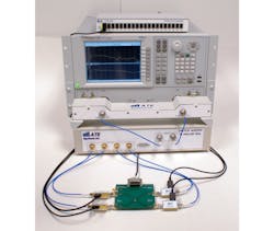
2. This is an example of a measurement system using the automatic calibration solution.
One of the benefits of using an automated calibration approach is the convenience of programmable software. For ATE Systems’ automated calibration solutions, the control operating software, which can be loaded into the measurement analyzer (VNA) or into the system controller, is based on Standard Commands for Programmable Instruments (SCPI) commands. It is also compatible with Virtual Instrument Software Architecture (VISA) code and drivers and includes instrument wrappers for use with LabVIEW/CVI test software from National Instruments.
Related Articles
• Vector Network Analyzers Support Versatile Testing
• Balanced Amplifier Aims For Low Noise
• VNA Modules Aid Antenna Testing
The software can run TCP/IP over Ethernet and incorporates an Internet browser interface to configure the controller module. The programmable software supports automated calibration routines using Tru Cal calibration software from Tru-Cal Metrology. It also features an Application Programming Interface (API) for use with all ATE calibration algorithms based on standard Windows 32 (WIN32) dynamic-link-library (DLL) code. The software, which is built upon rudimentary C data types for maximum compatibility, can be called from any programming language/IDE that supports DLL access, such as C, C++, LabVIEW, CVI, or Virtual Basic.
Of course, while proper calibration techniques can minimize systematic errors in a measurement setup, they do not address random errors. It is difficult to eliminate these errors, which originate from such sources as noise and environmental effects, but they can be minimized. Noise issues such as electromagnetic interference (EMI) can be reduced by means of shielding materials, and maintaining a narrow operating temperature range can reduce temperature effects on the measurement environment. In addition, by employing averaging and narrow IF bandwidths during calibrations and measurements, high measurement accuracy can be achieved and maintained. The use of automated calibration systems and techniques can certainly simplify the process of maintaining that high measurement accuracy.
Roy Zohrabian, Business Development Manager
ATE Systems, 85 Rangeway Rd., Building 1, North Billerica, MA 01862; (978) 362-1850.
This file type includes high resolution graphics and schematics.
