Making Microwave Measurements Modular
Test instrument modules once represented a small, specialized area among high-frequency measurement products. But more and more manufacturers are now supporting established module standards—such as PCI eXtensions for Instrumentation (PXI)—with a growing number of measurement functions. As a result, engineers are discovering that they can benefit from the versatility of modular test instruments without sacrificing performance compared to standard-sized rack-mount instruments.
The simplest trend to note in modular instruments is that their numbers are increasing rapidly. Since National Instruments (www.ni.com) created the specifications for PXI instrumentation in the late 1990s, the open PXI standard has gained momentum. Much of the credit for this goes to the PXI Systems Alliance industry group (PXISA; www.pxisa.org), now with more than 50 member companies. PXI Instruments use the Peripheral Component Interconnect (PCI) bus together with modular Eurocard mechanical packaging, in contrast to more traditional rack-mount instruments using the General Purpose Interface Bus (GPIB) for control and data communications. While a PXI mainframe may mount in a rack in the same way as a traditional stand-alone instrument, the different is that the mainframe’s functionality can be changed by changing slide-in modules and the software that controls them.
PXI instruments are built into either 3U or 6U Eurocards, where each U is 1.75 in. (44.45 mm) high and represents a rack unit or slot in a mainframe or chassis. Common PXI chassis sizes range from 4 to 18 slots, with some of the slots occupied by essential functions such as power supplies and system controllers. The chassis contains the PXI backplane with the PCI, triggering, and timing buses, and uses a dedicated 10-MHz system reference clock. Because the PXI backplane was defined with a somewhat limited bandwidth of 132 MB/s, the PXI standard evolved into a higher-speed standard (PXI Express) with a backplane bandwidth to 6 GB/s. PXI Express also adopted a higher-speed differential 100-MHz reference clock for enhanced synchronization capabilities, using the differential interface for improved immunity to noise.
Software for PXI instruments is managed by the PXI Systems Alliance—with PXI software defining the frameworks for PXI systems, which are based on 32-b Microsoft Windows® operating systems. The software is designed for compatibility with most popular development environments, including Visual Basic and LabVIEW software from National Instruments. The goal for all PXI software and hardware is universal interoperability.
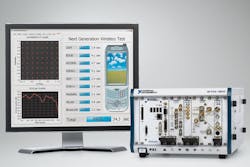
Hundreds of PXI instrument modules are currently available, many for RF/microwave measurement functions. Assembling a PXI or other modular measurement system starts with a mainframe/chassis designed to hold the modules. Next, modules are added to define desired measurement functions, such as signal generation and signal analysis. Control functions and measurements results are shown on a computer display screen in a PXI system (Fig. 1).
National Instruments offers both PXI and higher-speed PXI Express (PXIe) modules for a variety of functions, including chassis, system controllers, switches, signal sources, and digitizers/analyzers. Examples include the recently introduced PXI/PXIe-2543 multiplexer (a solid-state switch capable of routing signals to 6.6 GHz), the PXIe-5185/5186 digitizers, and the PXIe-5665 vector signal analyzer (VSA). The PXI/PXI-2543 is a 4 x 1 50-Ω multiplexer for high-density switching applications. It consists of dual single-pole, four-throw (SP4T) FET switches capable of operating from 10 MHz to 6.6 GHz with input power levels to +30 dBm. The insertion loss is typically less than 3.4 dB to 2.4 GHz and typically less than 6.1 dB through 6.6 GHz. VSWR is typically less than 1.50:1 through 2.4 GHz and less than 1.60:1 through 6.6 GHz. The isolation is better than 70 dB through 2.4 GHz and better than 59 dB through 6.6 GHz. Propagation delays are minimized to 1720 ps. The PXI/PXIe multiplexer boasts high dynamic range, with a typical 1-dB compression point of better than +32 dBm and typical input third-order intercept point of better than +54 dBm.
The PXIe-5185 and PXIe-5186 digitizers were co-developed by National Instruments and Tektronix (www.tek.com), with Tektronix contributing high-speed front-end application-specific integrated circuits (ASICs) based on a silicon-germanium (SiGe) semiconductor process. The dual-channel PXIe digitizers operate with sampling rates of 6.25 GSamples/s for two channels and 12.50 GSamples/s for one channel, with 8-b vertical resolution. The PXIe-5185 captures signals from DC to 3 GHz, while the PXIe-5186 operates from DC to 5 GHz across an input range of 110 to 1000 mV. The VSWR is typically 1.25:1 at 1 GHz and 1.80:1 at 5 GHz. Low integrated sampling jitter of 50 fs root mean square (RMS) results in 5.5 b effective number of bits (ENOB) at 5 GHz. The PXIe modules transfer data to a controller at rates to 700 Mb/s. Both digitizers are supplied in three-slot 3U PXI modules.
The PXIe-5665 VSA consists of three separate PXIe modules: a PXIe-5653 frequency synthesizer as the local oscillator (LO), a PXIe-5603 RF downconverter, and a PXIe-5622 IF digitizer. The modules combine for a low-frequency path that covers 20 Hz to 3.6 GHz and a high-frequency path that extends to 14 GHz. The trio of modules, which can be used as a spectrum analyzer as well as a VSA, provides instantaneous bandwidths of 25 and 50 MHz with 16-b resolution and better than -165 dBm/Hz typical displayed average noise level (DANL) at 1 GHz. The amplitude accuracy is typically ±0.1 dB with ±0.35 dB typical amplitude flatness within a 20-MHz bandwidth. The typical phase noise is -129 dBc/Hz offset 10 kHz from an 800-MHz carrier.
Phase Matrix (www.phasematrix.com) offers a full line of PXI modular instruments, including tunable preselector filters, frequency downconverters, and microwave LOs, in 3U sizes occupying from one to three slots in a PXI chassis. For example, model PXI-1450B is a two-slot PXI LO module with frequency range of 3 to 9 GHz and 1-Hz tuning resolution. It has 500-µs frequency switching speed and as much as +16 dBm output power with ±2 dB amplitude accuracy. Spurious levels are suppressed to -60 dBc and phase noise is -115 dBc/Hz offset 10 kHz from a 9-GHz carrier.
ZTEC Instruments (www.ztechinstruments.com) produces a 6-GHz VSA in both PXI and PXIe formats. Models ZT 8651 PXI and ZT 8651 PXIe both feature frequency spans of DC to 6 GHz with amplitude capture ranges of -120 to +20 dBm. They operate at 400 MSamples/s with 16-b resolution and use a high-speed FPGA for real-time signal processing. The VSAs provide 1-Hz frequency resolution and phase noise of better than -125 dBc/Hz offset 100 kHz from a 1-GHz carrier. Low-level signals benefit from an 80-dB SFDR and DANL of -163.5 dBm/Hz at 6 GHz. Modulation can be analyzed by means of differential I and Q input ports and an instantaneous bandwidth of 160 MHz.
GuideTech (www.guidetech.com) offers a number of PXI chassis products, as well as its continuous-time-interval-counter (CTIA) line of PXI instruments through 2.7 GHz. The latest model, the GT210PXI-8, offers automatic measurements of time interval, frequency, period, totalize, ratio, time interval delay, and pulse width across eight channels. It provides 0.01 ppm frequency resolution and 8-ps time resolution, and can perform 2300 measurements/s. It is supplied in a 3U PXI module form factor.
Aeroflex (www.aeroflex.com) has developed a variety of PXI instruments, including its models 3010 and 3011 frequency synthesizers, each fitting into single-width 3U PXI cards. They tune from 12.50 to 3.0 GHz with 1-Hz frequency resolution and typical phase noise of -116 dBc/Hz offset 20 kHz from the carrier. The phase noise for both units is -114 dBc/Hz offset 10 kHz from the carrier and typically -140 dBc/Hz offset 1 MHz from the carrier. The modules differ by degree of stability: the 3010 derives its stability from an internal voltage-controlled crystal oscillator (VCXO) or external 10-MHz reference oscillator, while the 3011 operates with an internal 10-MHz oven-controlled crystal oscillator (VOCXO) reference. The PXI synthesizers deliver -4 to +3 dBm output power and switch frequencies with 1.1-ms typical frequency settling time.
Agilent Technologies (www.agilent.com) supplies numerous instruments in the PXI format, but is also one of a growing number of companies to offer instruments in the AXIe modular format. Agilent’s model M9392A is the industry’s most broadband PXIe VSA with a bandwidth of 50 MHz to 26.5 GHz. Available in a two-channel version that fits neatly in the firm’s M9018A 18-slot PXIe chassis (Fig. 2) and works under the command of the 89600 VSA software, the PXI VSA boasts an instantaneous bandwidth of 250 MHz. The PXI format makes such functionality possible in a compact enclosure. The VSA contains several IF digitizers, a pair of frequency downconverters, an LO module, an attenuator/preselector-filter module, and a controller module—or, in traditional instruments with equivalent functionality, a large, 19-in.-wide rack full of instruments. The VSA incorporates an internal 10-MHz reference oscillator with ±1 ppm/year aging rate and achieves ±0.5 dB amplitude accuracy to 26.5 GHz. It has a DANL of -158 dBm/Hz to 9.5 GHz and -147 dBm/Hz to 26.5 GHz, with phase noise of -115 dBc/Hz offset 10 kHz from a 10-GHz carrier.
The company also supports the emerging AdvancedTCA Extensions for Instrumentation and Test (AXIe)modular instrumentation standard. AXIe leverages elements of existing standards, including AdvancedTCA, PXI, and LAN eXtensions for Instrumentation (LXI). The open standard is supported by its own standards organization (www.axiestandard.org). It is meant to support applications that require high power dissipation or high processing speeds, such as when a large number of interconnections are needed. Agilent offers chassis products as well as instruments, such as the model M9703A AXIeeight-channel digitizer (Fig. 3). The single-slot 12-b digitizer has an analog bandwidth of DC to 1 GHz and operates at sampling rates to 3.2 GSamples/s. The compact AXIe module includes four Virtex-6 FPGAs from Xilinx (www.xilinx.com) and 4 GB internal memory for robust signal analysis and processing. It has a full-scale sampling range to 1 or 2 V, with a -60 dBc SFDR and 8.8-b ENOB.
The firm is not alone in offering AXIe modules, with companies such as Aeroflex also producing AXIe test equipment products. Guzik (www.guzik.com) is also one of an increasing number of computers to support the newest instrument module format, with its ADC 6000 series of AXIe digitizer modules. With one- to four-channel models with sampling rates to 40 GSamples/s (for one channel) and bandwidths to 13 GHz, these modules offer deep memories for complex signal capture, as much as 16 GB per channel for four-channel units, and as much as 64 GB memory for single-channel digitizers.
In terms of PXI, PXIe, and AXIe modular instruments, the list steadily grows longer. Additional suppliers include Geotest (www.geotestinc.com), Pickering Interfaces (www.pickeringtest.com), and VTI Instruments (www.vtiinstruments.com). Those accustomed to traditional instruments may doubt the capabilities of modular test equipment; nonetheless, modular instruments can provide excellent results while passing test data at high speeds for high-volume, production-line measurements.
About the Author
Jack Browne
Technical Contributor
Jack Browne, Technical Contributor, has worked in technical publishing for over 30 years. He managed the content and production of three technical journals while at the American Institute of Physics, including Medical Physics and the Journal of Vacuum Science & Technology. He has been a Publisher and Editor for Penton Media, started the firm’s Wireless Symposium & Exhibition trade show in 1993, and currently serves as Technical Contributor for that company's Microwaves & RF magazine. Browne, who holds a BS in Mathematics from City College of New York and BA degrees in English and Philosophy from Fordham University, is a member of the IEEE.
