Digital Predistortion Linearizes RF PAs

This file type includes high resolution graphics and schematics.
Wireless communications standards continue to evolve to meet growing demands for transmitting and receiving voice, data, and video signals. As an example, the cellular LTE-Advanced (LTE-A) standard has been created and expanded for worldwide access and global roaming in a variety of wireless services.1 To boost capacity, the maximum transmission bandwidth of LTE-A can be increased to 100 MHz by employing spectrum aggregation technology.2-4 But as transmission bandwidths increase, so, too do the challenges to provide cellular base-station power amplifiers (PAs) capable of the linearity, efficiency, and output power to support these expanding wireless standards. Efficiency is of particular concern, as it impacts not only performance but also system operating costs.
Related Articles
• Blocking Caps Boost Power Amplifiers
• Amplifiers Power 20 To 1000 MHz
• Simulate A Doherty Amplifier With DPD
Several methods for improving PA efficiency have been investigated, such as the use of Doherty amplifier formats, linear amplification using nonlinear components (LINC), and envelope elimination and restoration (EER) approaches. Doherty amplifiers are attractive for their relative low cost, simple fabrication, and only moderate complexity. But improving the linearity of these amplifiers is also an important requirement for these systems. A number of newer technologies have been applied to improving PA linearity, including the use of RF predistortion, digital baseband predistortion, feed-forward techniques, and feedback techniques. Among these different approaches, digital baseband predistortion shows great promise for achieving good amplifier performance with low cost and flexible implementation.
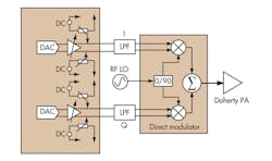
Figure 1 shows a block diagram for a high-frequency PA with a digital baseband predistortion linearization scheme. A digital baseband predistortion module generates an in-phase/quadrature (I/Q) predistortion signal which is the exact inverse of the PA’s baseband I/Q response. The direct modulator converts the I/Q predistortion signal to an RF/microwave signal. The direct modulator is used to capture the output of the PA with the predistortion signal characteristics. A Doherty PA is used as part of the block diagram for its good wideband performance and high efficiency.
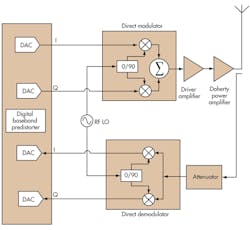
1. This block diagram shows an LTE-A PA with of digital baseband predistortion linearization scheme.
The modulator and demodulator in the block diagram can be replaced by an intermediate-frequency (IF) transceiver. An analog-to-digital converter (ADC) capable of digitizing the output signals from an LTE-A amplifier is difficult to realize at this frequency and bandwidth. As a result, a direct modulator and demodulator make more sense for the wideband linearization of an LTE-A PA. As the bandwidth of the PA and the system increase, the performance levels of the modulator and demodulator become more critical to performance of the amplifier and the system. To better understand the relationships of the direct modulator and demodulator on the linearization of the PA, the key I/Q parameters affecting the modulator and demodulator were simulated and analyzed in order to develop a novel linearization approach for an LTE PA with 100 MHz digital baseband bandwidth. By means of these simulations and experimental results, it was found that an LTE-A PA with 100-MHz bandwidth can achieve an adjacent-channel power ratio (ACPR) of -48 dBc.
This file type includes high resolution graphics and schematics.
The DCT Approach
This file type includes high resolution graphics and schematics.
Direct-conversion-transmitter (DCT) technology has been applied with some success in PA linearization. It can bring high linearity without high cost or complexity, supporting the design of compact PAs with excellent performance. In this approach, digital I and Q signals pass through a high-speed digital-to-analog converter (DAC) for conversion into analog baseband signals. These analog I/Q baseband signals then directly modulate the RF carrier for processing and transmission by the PA. In this approach, output signals from a Doherty PA are demodulated to I/Q baseband signals for processing by a digital baseband predistortion circuit. Unfortunately, this approach cannot overcome I/Q imbalance, unwanted sideband content, and LO leakage, all of which can degrade transmitter performance.
Related Articles
• Blocking Caps Boost Power Amplifiers
• Amplifiers Power 20 To 1000 MHz
• Simulate A Doherty Amplifier With DPD
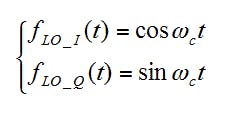
As part of a theoretical analysis, the phase and amplitude of the baseband in-phase and quadrature signals, I(t) and Q(t) will be perfectly matched, as will the LO quadrature signals fLO_I(t) and fLO_Q(t). For such an analysis, the RF signal fRF(t) is an ideal single-sideband signal without image components, and without LO leakage or any form of phase and amplitude imbalance. However, some imperfections—such as the DC offset and the imbalance of signal components I(t) and Q(t) in amplitude and phase—will remain uncorrected. To simplify this theoretical analysis, allow the practical signal components I(t), Q(t), fLO_I(t), and fLO_Q(t) to be expressed as follows5:
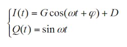
where:
G = the amplitude imbalance ratio;
φ = the quadrature phase offset of I to Q; and
D = the DC offset of the I to Q signal components.
Under ideal conditions, G = 1, φ = 0, and D = 0:
Following the direct-conversion transmitter, the output signal f(t) can be expressed as:
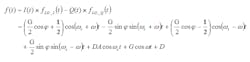
The output RF signal includes an up-band signal component, a down-band signal component, local oscillator (LO) leakage, and low-frequency signal components. If the signal is passed through a bandpass filter, the low-frequency signal components can be removed. However, the down-band signal LO leakage will still be part of the signal. Deducing from the above relationships, the I(t) and Q(t) imbalance in amplitude, phase, and DC offset will result in degradation of the modulated signal quality, deteriorating the performance of an LTE signal generator.

2. This schematic diagram shows the setup for the PA EVM simulation performed with Advanced Design System (ADS) simulation software.
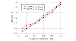
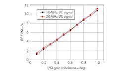
Imbalances in amplitude, phase, and DC offset at baseband will impact the signal requirements for achieving a properly linearized PA. To better understand performance data from error vector magnitude (EVM) analyses, simulation results using the Advanced Design System (ADS) simulation software from Agilent Technologies were studies according to the schematic diagram of a PA EVM simulation in Fig. 2. Figures 3 and 4 show I/Q gain and phase imbalance affecting LTE EVM. The simulations also illustrate how the linearity performance will degrade with an increase in amplifier bandwidth. In addition, the DC offset will also affect the I/Q modulation quality.
3. Baseband I/Q amplitude imbalance can ultimately degrade the EVM performance of an LTE-A amplifier and system.
4. Baseband I/Q phase imbalance can ultimately degrade the EVM performance of an LTE-A amplifier and system.
Similar approaches to the analysis and simulation were used for the demodulator. Imbalances in I/Q amplitude, phase, and DC offset were also found to affect the linearity performance of the PA when related to the demodulator. But by adopting a novel approach that attempts to provide “correction” signals to the modulator and demodator, it may be possible to improve the linearity performance of an LTE-A PA.
5. This diagram shows a novel approach for improving the linearity quality of a cellular PA.
Figure 5 illustrates the novel approach for enhancing the performance of the I/Q modulator and demodulator with the intention of improving the linearity performance of the LTE-A PA. As the diagram shows, eschewing the conventional, single-baseband input signal for a second baseband signal (achieved by means of an additional operational amplifier) makes it possible to adjust the I/Q amplitude, phase, and DC offset content of the baseband signals.
Experimental results of a system based on this block diagram using this digital baseband predistortion linearization PA are tested by a model E4438 signal generator and 89600 vector signal analysis software from Agilent Technologies. Figure 6 shows the performance of the 100-MHz modulator in this experimental system, while Fig. 7 shows the demodulator EVM for a 100-MHz baseband signal.
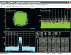
6. This plot shows the quality of the I/Q modulator working at 3.45 GHz.
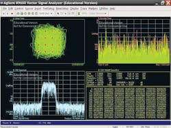
7. This plot shows the quality of the I/Q demodulator working at 3.45 GHz.
This digital baseband predistortion linearization scheme was tested with a practical Doherty PA with the results shown in Fig. 8. By using the accuracy-improved I/Q modulator and demodulator (with the aid of the additional operational amplifier), it was possible to achieve an ACPR of -48 dBc for a 100-MHz baseband LTE-A signal, while maintaining PA efficiency of 40%.
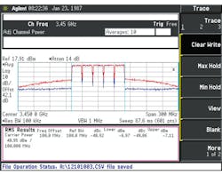
8. This plot shows the measured ACPR of the LTE-A PA with digital baseband predistortion linearization.
Ling Tian, Engineer/Researcher
Lei Zhang, Engineer/Researcher
Jianfeng Zhai, Engineer/Researcher
Jin Xia, Engineer/Researcher
Xiaowei Zhu, Engineer/Researcher
State Key Laboratory of Millimeter Waves, School of Information Science and Engineering,
Southeast University, Nanjing, People’s Republic of China, e-mail: [email protected], www.seu.edu.cn.
References
1. T Ojanperä and R. Prasad, Wideband CDMA for Third Generation Mobile Communications, The Artech House Universal Personal Communications Series, Artech House, Norwood, MA, 1998.
2. 3GPP technical standard: TS 25. 104 V6. 4. 0 base station (BS) radio transmission and reception (FDD), www.3GPP.org.
3. 3GPP2 technical standard: C. S00102C recommended minimum performance standards for cdma2000 spread spectrum base, www.3GPP.org.
4. 3GPP technical standard: TS 25. 105 V6. 2. 0 base station (BS) radio transmission and reception (TDD), www.3GPP.org.
5. Cao Peng, Li Weiqiang, Qi Wei, and Fei Yuanchun,” Key Techniques in Research and Implementation of the Direct Quadrature Concersion Transceiver,” Chinese Journal of Electronics, Vol. 13, No. 4, October 2004.
This file type includes high resolution graphics and schematics.
