Generating Reliable RF/Microwave Signals
Oscillators are key components in RF/microwave systems, signal sources that must remain stable across a wide range of operating conditions. They come in many shapes and sizes, with either fixed or variable frequencies, in many different package types (even as circuit modules), and from a large number of suppliers. As with choosing any high-frequency component for a design, selecting an RF/microwave oscillator comes down to matching the lowest cost possible while achieving the required performance levels for an application. Knowing which performance parameters are the most critical for that application is equally critical.
Related Articles
• Tunable Oscillators Cover Multiple Bands
• Tunable Oscillator Stifles Phase Noise
• Oscillators Cover Multiple Bands
There is no “ideal” oscillator for high-frequency use, since the many types of oscillators used for RF/microwave applications offer a variety of functions and performance levels. Perhaps the most common type of oscillator is the fixed-frequency reference or clock oscillator, typically used to stabilize the phase of a higher-frequency tunable-frequency oscillator. Clock oscillators come in many configurations, including those with some form of compensation to correct for the frequency-shifting effects of temperature changes.
Examples of these are temperature-compensated crystal oscillators (TCXOs) and oven-controlled crystal oscillators (OCXOs). Such oscillators can almost universally be found in RF/microwave test equipment, such as signal generators and spectrum analyzers—often as 10-MHz reference sources.
These reference oscillators are noted for their frequency stability. They are characterized in terms of their phase-noise performance, typically at different offset frequencies from a carrier (such as 1 kHz, 10 kHz, and 1 MHz). This phase/frequency stability can serve as a reference for a higher-frequency oscillator, essentially locking its phase characteristics to those of the lower-frequency reference source.
In comparing different crystal oscillators, key performance specifications include frequency stability; aging rate or amount of frequency change with time (which may be given per day, per year, or even per 10 years); operating temperature range; available frequency tuning range; warmup time; power consumption; phase noise; spurious; and harmonic levels. Additional critical performance parameters include frequency pulling (the change in frequency as a result of the load impedance) and frequency pushing (the change in frequency due to variations in the oscillator’s power supply).
At higher frequencies, the number of oscillator choices increases dramatically. They range from oscillators based on traditional voltage-controlled-oscillator (VCO) architectures to more exotic resonator structures, including surface-acoustic-wave (SAW) and yttrium-iron-garnet (YIG) resonators. All of these tunable RF/microwave oscillators exhibit some form of tradeoff in performance. Typically, slower-tuning oscillators, such as YIG oscillators, achieve somewhat better phase-noise characteristics than faster-tuning oscillators, such as VCOs.
In terms of packaging, many of these higher-frequency RF/microwave oscillators have been designed in recent years into compact packages, such as TO-8 housings (along with even smaller options), without sacrificing mechanical-related or temperature-based frequency/phase stability.
Dielectric-resonator oscillators (DROs), for example, are commonly used in communications systems throughout the microwave frequency range (3 through 30 GHz). They are based on a puck of ceramic material with high dielectric constant and high circuit quality factor (Q). The resonant frequency for a particular oscillator design is determined by the physical dimensions of the puck and the dielectric constant of the puck’s material.
The resonant properties of DROs have often been compared to those of circular waveguide at microwave frequencies, with one exception: The electromagnetic (EM) fields within a circular waveguide are contained within that cavity, while the EM fields produced within a dielectric puck continue beyond the puck. This requires a DRO to be enclosed within a conducting cavity for most applications. The presence of the DRO’s housing, or boundary conditions, must be considered when determining the frequency of an oscillator for given mechanical and electrical conditions.
Comparison Criteria
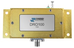
DROs can be problematic in terms of their sensitivity to temperature variations and mechanical vibrations. When comparing different models, key specifications include frequency, frequency stability with temperature, output power, output-power variations, phase noise, spurious levels, harmonic levels, physical size, and power consumption. As a commercial example, model DRO100 from Synergy Microwave Corp. (Fig. 1) is a 10-GHz DRO supplied in a compact, lead-free, RoHS-compliant metal package with SMA connector. It provides at least +8 dBm output power at 10 GHz and tunes with voltages of +1 to +15 VDC, along with typical tuning sensitivity of 3 MHz/V.
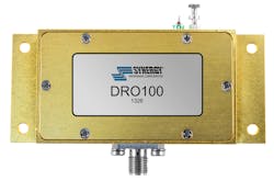
1. Model DRO100 is a 10-GHz DRO supplied in a lead-free, RoHS-compliant metal package. (Photo courtesy of Synergy Microwave Corp.)
Harmonics are typically -40 dBc while phase noise is typically -81 dBc/Hz offset 1 kHz from the carrier, -111 dBc/Hz offset 10 kHz from the carrier, and -156 dBc/Hz offset 1 MHz from the carrier. The DRO draws 70 mA current from a bias supply of +7 to +10 VDC and is designed for operating temperatures from -15 to +75°C.
Of course, there are many alternative oscillator technologies available for providing a 10-GHz signal, including YIG oscillators and VCOs. Each approach is noteworthy for a particular performance benefit—e.g., YIG oscillators for their low phase noise and VCOs for their fast tuning and settling times. For an application where frequency agility is a key requirement, for example, a first step might involve a comparison of available VCOs across the frequency tuning range of interest, with that comparison also including critical specifications such as phase noise, spurious levels, and harmonic levels.
As an example, model DCO400800-5 from Synergy is a VCO housed in a tiny surface-mount package measuring just 0.3 x 0.3 in (Fig. 2). It tunes from 4000 to 8000 MHz and draws just 20 mA at +5 VDC. It delivers at least -3-dBm output power over the frequency range with typical tuning sensitivity of 120 to 620 MHz/V. The phase noise is typically -80 dBc/Hz offset 10 kHz from the carrier, -105 dBc/Hz offset 100 kHz from the carrier, and -125 dBc/Hz offset 1 MHz from the carrier. The VCO is designed for use from -40 to +85°C.
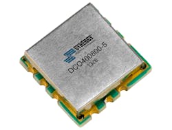
2. This VCO tunes from 4 to 8 GHz in a surface-mount package measuring just 0.3 x 0.3 in. (Photo courtesy of Synergy Microwave Corp.)
YIG oscillators are based on single-crystal YIG spheres which resonate within an applied magnetic field, allowing frequency tuning over wide ranges at microwave frequencies. Quite simply, the resonant frequency increases as the applied magnetic field strength increases. YIG oscillators have been formed with both permanent magnets and with electromagnetic designs, with the field strength of the electromagnet and its main coil winding a direct function of the applied current.
Related Articles
• Tunable Oscillators Cover Multiple Bands
• Tunable Oscillator Stifles Phase Noise
• Oscillators Cover Multiple Bands
There are limits to the size of the magnetic field—and the highest tuning frequency—that can be achieved for a given YIG oscillator housing. Oftentimes, a secondary coil winding must be incorporated within the package to achieve frequency modulation (FM). In some cases, heating circuits may also be built into a YIG oscillator to stabilize frequency over a broad operating temperature range. Advances in YIG oscillator (and filter) technology in recent years have made possible compact YIG sources that can fit within TO-8 packages.
At the highest frequencies, specifiers usually reach for Gunn oscillators. These are based on a Gunn diode mounted inside a mechanical cavity, which functions as the resonator. Such sources are commonly found in millimeter-wave applications, with Gunn oscillators using GaAs semiconductor technology reaches to frequencies of 100 GHz and higher. Gunn oscillators with gallium nitride (GaN) and other semiconductor technologies reach well into the THz frequency range.
About the Author
Jack Browne
Technical Contributor
Jack Browne, Technical Contributor, has worked in technical publishing for over 30 years. He managed the content and production of three technical journals while at the American Institute of Physics, including Medical Physics and the Journal of Vacuum Science & Technology. He has been a Publisher and Editor for Penton Media, started the firm’s Wireless Symposium & Exhibition trade show in 1993, and currently serves as Technical Contributor for that company's Microwaves & RF magazine. Browne, who holds a BS in Mathematics from City College of New York and BA degrees in English and Philosophy from Fordham University, is a member of the IEEE.
