Test High-Power RF/Microwave From Tower To Tabletop
This file type includes high resolution graphics and schematics when applicable.
It has been several decades since vacuum tubes, cat’s whisker detectors, and water-flow calorimeters were the dominant options for measuring RF/microwave power. In that bygone era, power-measurement technology could only describe the average amount of radiation absorbed by a simple detector. With complex modulation techniques and the need to measure powerful signals on integrated substrates, power measurements have obviously become much more sophisticated. At the same time, spectrum congestion has increased the monitoring and design precision of high-power amplifiers to prevent interference with other transmitters and telecommunications cells.
Related Articles
• High-Voltage GaN-on-Si Devices Deliver High Power
• Amps Pack High Power To 1 GHz
• Resistors Handle High Power Levels
There are several methods of measuring RF/microwave power signals. Direct sensing methods—such as thermal measurements from the heating effect upon a sensing area or detecting a signal with diodes—create a direct-current (DC) voltage proportional to the signal amplitude. These methods are common in scenarios where the absolute signal power is needed and the signal power is extremely high. Indirect methods are used where the high-precision characterization of RF/microwave devices and knowledge of the modulated signal power are necessary.
An indirect receiver method consists of a tuned circuit that measures the signal’s amplitude component. Another indirect method is the digitization of the signal, known as sampling. Indirect methods use advanced test equipment, which can bring a captured signal into a processing domain for analysis after detection. These test typologies enhance the test accuracy of power signals with advanced modulation.
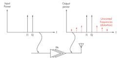
Multiplexing methods, such as time-domain multiplexing, are designed to enable multiple devices to communicate on the same upstream channel simultaneously. Real-time measurements of the signal path are necessary to properly monitor the multiplexed signals. If one of the multiplexed signals, for example, were to significantly exceed the others in power, it could prevent the reception of the other signals. Several integrated-circuit (IC) detectors designed to solve this problem are receive signal strength indicators (RSSIs), root-mean-square (RMS) voltage detectors, analog multipliers, and demodulating logarithmic amplifiers (Fig. 1).

These devices convert the signal amplitude into a proportional DC signal. Generally, such devices have nonlinear response curves and require calibration. In addition, they fail to provide true power measurements in lieu of voltage detection. Other methods that provide information based on the signal amplitude involve more complex electronics. These devices and techniques are used to gain knowledge of the devices in the signal stream before broadcasting to ensure proper operation.
If a signal’s carrier frequency is slow enough to allow for direct digitization, the signal can be re-created digitally and analyzed. This is the process by which direct storage oscilloscopes operate. For wideband modulated signals, the ability to sample a signal needs to be around 10 times the carrier frequency. For modern telecommunications and radar systems, this method would require extremely fast sampling devices—which could, in turn, mean an expensive solution. With phased-array radars pulsing at higher frequencies with narrower pulses—and with the telecommunications spectrum density increasing—there is demand for more precise methods of characterizing and measuring the power response of electronic devices.
Hiro Maehara, product marketing engineer/application expert, Component Test Division of Agilent, shares his insights into devices in high-power RF/microwave signal streams: “All components in transmitters used in high-power applications, such as wireless base stations, point-to-point communications, satellite communications both in ground stations and payloads, transmit/receive modules used in radar applications, and more require testing. These components include amplifiers, mixers, converters, circulators/isolators, attenuators, connectors, cables, etc.”
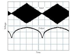
To conduct the testing and measurement of power signals and power devices in a closed-loop and open-loop environment, tools like vector network analyzers (VNAs), vector signal analyzers (VSAs), and signal analyzers (SAs) are used to better understand the dynamic parameters of powerful RF/microwave devices. VNAs are predominantly used for characterizing a device’s S-parameter, stability, power leveling, gain compression, pulsed-RF, and intermodulation distortion (IMD) measurements on devices like power amplifiers (PAs; Fig. 2).
Generally, VSAs are used to measure a known signal’s error vector magnitude, spectral flatness, and code domain power to ascertain the quality of the modulated signals. Spectrum analyzers sweep their full frequency range for the power level of signals and produce a response that measures dominant frequency, power, distortion, harmonics, bandwidth, and other frequency-domain components.
This file type includes high resolution graphics and schematics when applicable.
Weakening Signals
This file type includes high resolution graphics and schematics when applicable.
These high-precision instruments cannot handle significant power levels. As a result, components like attenuators, directional couplers, and loads are necessary to weaken the signals prior to reception. This process adds additional error, inaccuracies, nonlinearities, and potential distortion factors into the test signal paths. For high-power test, directional couplers are sometimes preferred over attenuators, as fixed attenuators for high power change in performance as power levels and case temperatures change. When primarily using directional-coupler test systems, a load termination is necessary to deplete the remaining signal energy.
This can enable highly accurate measurements, as directional couplers exhibit low insertion loss, high directivity, and high stability. But the termination load could introduce intermodulation distortion and add to the voltage standing wave ratio (VSWR). Both components use coaxial connectors at the interface between devices. It is important to remember that the connectors’ power-handling capability changes as a function of frequency (Fig. 3).

In some high-power systems, both attenuators and directional couplers are necessary to create a test setup like a telecommunications transmitter. To avoid compounding errors and distortion, the configuration of the test setup is critical. Maehara explains, “It is best to place test couplers right at the DUT input and output for network analysis. Attenuators are placed between the coupler’s output and the instrument input port.” Using this approach will prevent the attenuator from hiding the device response while it protects the test equipment from high power levels.
Going into examples, Maehara notes that a reference coupler for measuring the stimulus in network analysis is best placed after a boost amplifier in a transceiver configuration. Another tip is that the use of attenuators at the outputs of a boost amplifier will reduce mismatch in the measurement path. These methods work for larger systems with high power. But testing high power levels on integrated components requires an advanced set of tools that can interface with small-scale devices.
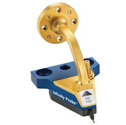
Compounding all of today’s test requirements is the fact that RF/microwave devices are being combined and compacted into ever-smaller footprints. Material technologies and advanced processes are enabling higher-frequency and higher-current operation on ICs. High-power and high-frequency test instruments must therefore be adapted to the surface of a wafer. Companies like Cascade and Picoprobe offer specialized probe heads for measuring high-density, power, and frequency signals from the wafer surface. These companies, among others, offer sophisticated probe platforms for proper temperature dissipation, vibration reduction, and backside connections.
Such probing devices require high power handling, high current handling, low/stable contact resistance, and low insertion loss. Among the challenges they face are maintaining reliable contact with oxide development on probe pads, the bending of very thin wafers, thermal shifts, and enabling millimeter-wave frequencies with reasonable power in compact probes. The solutions currently offered in the marketplace include probes to 110 GHz, vacuum chucks, thermally regulated chucks, and probes with built-in waveguide converters (Fig. 4).
Related Articles
• High-Voltage GaN-on-Si Devices Deliver High Power
• Amps Pack High Power To 1 GHz
• Resistors Handle High Power Levels
Clearly, when applying RF, microwave, and millimeter-wave signals, significant care is needed when planning the devices and interconnects of a system. This process—called power budget analysis—involves a detailed breakdown of every device’s and connection’s power-handling capability. The maximum expected power levels throughout the signal path must be known for effective power-budget analysis. Ensuring that each individual component rating complies with the signal power levels is critical in avoiding ineffective testing, device failure, and even health hazards.
Thermal management of attenuating and amplifying components is another necessary aspect of high-power system design. As most electronics properties drift with temperature, regulating the temperature within operating norms is a critical aspect of system reliability. This problem becomes more complex as these previously discrete components are integrated into a monolithic or even stacked-IC typology. Examples of software packages that simulate thermal dissipation and generation for modern RF/microwave ICs are Tecnode’s Symmic software, ANSYS’s RF & Microwave software, and Silvaco’s Thermal 3D.
This file type includes high resolution graphics and schematics when applicable.
About the Author
Jean-Jacques DeLisle
Jean-Jacques graduated from the Rochester Institute of Technology, where he completed his Master of Science in Electrical Engineering. In his studies, Jean-Jacques focused on Control Systems Design, Mixed-Signal IC Design, and RF Design. His research focus was in smart-sensor platform design for RF connector applications for the telecommunications industry. During his research, Jean-Jacques developed a passion for the field of RF/microwaves and expanded his knowledge by doing R&D for the telecommunications industry.
