Perusing Materials For High-Frequency PCBs
This file type includes high resolution graphics and schematics when applicable.
Circuit materials for printed-circuit boards (PCBs) are crucial building blocks for RF/microwave circuits—in essence, the starting points for those circuits. PCB materials are available in many different forms, and the choice of material is very much dependent upon the requirements of the intended application. For example, materials that dependably support high-frequency circuits in commercial wireless products can fail quickly when thrust into the wide extremes of military environments. A basic understanding of PCB material types and their parameters can help match a material to an application.
Related Articles
• Technology Transforms Passive Components
• Benefit From High-Dk Microwave Circuit Materials
• Materials Support High-Speed Circuits
As with many RF/microwave components, PCB materials are sorted and compared by a number of key parameters, including relative dielectric constant (Dk or εr), dissipation factor (Df), coefficient of thermal expansion (CTE), thermal coefficient of dielectric constant (TCDk), and thermal conductivity. Many circuit designers start with Dk when sorting through different PCB materials. The Dk value of a PCB material refers to the capacitance or energy available between a pair of conductors in close proximity fabricated on that material, compared to the same pair of conductors in a vacuum.
The vacuum yields a reference value of 1.0, with other dielectric materials delivering somewhat higher values. For example, the Dk values of commercial PCB materials typically range from about 2 to 10, depending on how they are measured and at which test frequency. Conductors on materials with higher Dk values can store more energy than on materials with lower Dk values.
The value of a PCB material’s Dk impacts the dimensions, wavelengths, and characteristic impedances of transmission lines fabricated on that material. For a given characteristic impedance and wavelength, for example, the dimensions of transmission lines fabricated on a PCB material with high Dk value will be considerably smaller than those for transmission lines fabricated on a PCB material with lower Dk value, although other material parameters may be different. Designers faced with circuits where loss is a critical performance parameter will often lean towards using PCB materials with lower Dk values, since those materials exhibit lower loss than higher-Dk materials
In truth, a PCB material can lose signal power in four ways—through dielectric, conductor, leakage, and radiation losses—although dielectric and conductor losses are more controlled via the choice in PCB material. The Df parameter, for example, provides a means of comparing the dielectric losses of different materials, with lower Df values indicating materials that have lower dielectric losses.
For a given transmission-line impedance, such as 50 Ω, transmission lines will be physically wider on a lower-Dk material than on a higher-Dk material, with lower conductor losses for the wider transmission lines. These wider transmission lines can also translate into higher fabrication yields (and savings in production costs) than the narrower transmission lines of higher-Dk materials. As a tradeoff, however, they occupy more area on a PCB, which can be a concern for designs where miniaturization is important. The thickness of a PCB substrate—and in particular, the thickness of its copper conductor layer—will also affect the impedance of the transmission lines, with thinner dielectric materials and conductors yielding narrower conductor widths to maintain desired characteristic impedance.
Conductors for PCB materials are usually specified in terms of copper weights, such as 1-oz. (35-μm-thick) copper or 2-oz. (70-μm-thick) copper. The quality of these copper conductors will also affect conductor losses. A copper conductor with a rough surface will exhibit higher conductor losses than a copper conductor with a smooth surface profile.
Maintaining the impedance of transmission lines is critical to many RF/microwave circuits and, for that reason, controlling the Dk within a narrow range across a PCB and with temperature is essential for achieving tight impedance in a design. Most PCB data sheets present a material’s Dk along with its Dk tolerance, such as ±0.5.
This file type includes high resolution graphics and schematics when applicable.
Additional Parameters
This file type includes high resolution graphics and schematics when applicable.
Another important material parameter, TCDk, provides details on how much a PCB material’s Dk will change over an operating temperature range, as that can also impact the impedance of the transmission lines. A TCDk value of 150 ppm/°C might be considered high, while a value of 30 ppm/°C or less is considered low. For circuits in which impedance must be maintained over a wide range of operating temperatures, PCB materials with lower values of TCDk are to be preferred.
In addition to changes in temperature affecting Dk and impedance, they can also have mechanical effects on a PCB; a PCB’s CTE is a parameter that attempts to show some of the impact of temperature on a PCB material. Essentially, it is a measure of the expansion/contraction of a material with temperature, with lower numbers a target. For example, a material such as polytetrafluroethylene (PTFE) has long been used for high-frequency PCBs because of its excellent electrical characteristics, although pure PTFE has a high CTE (about 300 ppm/°C).
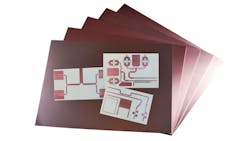
Some PCB material manufacturers, such as Rogers Corp., use PTFE in their materials but add different filler materials to reduce the CTE value (see photo). A concern is that the CTE of a PCB’s dielectric material should be closely matched to the CTE of its conductors and other layers, so that the mechanical effects of changes in temperature are minimized.

For any commercial PCB material, separate CTE values are usually listed for all three axes (x, y, and z). CTE provides some evidence as to how PCB materials will handle temperature extremes, such as during soldering operations. For example, mismatches in CTE values for materials used in multilayer constructions can lead to reliability problems as dimensional changes take place with temperature for the different circuit layers. PCB materials with lower CTE values are generally considered more thermally robust than materials with higher CTE values. A circuit material with CTE of 70 ppm/°C is considered fairly robust in terms of use over a wide temperature range and should be capable of handling the temperature extremes of circuit fabrication and assembly.
The CTE of a PCB material should be closely matched to that of copper in the x and y axes to minimize mechanical stress with temperature. In addition, the CTE in a circuit material’s z-axis provides some insight into the expected reliability of plated through holes (PTHs) that will be formed through the dielectric material, since these drilled holes are plated with copper. Ideally, the dielectric material and the copper will expand and contract with temperature in similar fashions for high reliability of the PTHs.
Dissipating heat from RF/microwave circuits, especially for high-power designs, is an important capability that is characterized by a PCB’s thermal conductivity. While standard PCB materials may have thermal conductivity of 0.25 W/m/K, fillers are often added to PCB materials to boost the thermal conductivity to more favorable values (and better capabilities for dissipating heat). As an example, RO4350B is a hydrocarbon/ceramic PCB material from Rogers Corp. that has long been a reliable building-block material for high-frequency applications, including in automotive and cellular-communications systems.
RO4350B is not based on PTFE, but exhibits a relatively low Dk of 3.48 ± 0.05 in the z-axis at 10 GHz with a TCDk of +50 pm/°C and dissipation factor of 0.0037. It features reasonably good thermal conductivity of 0.69 W/m/K. In contrast, RT/duroid 6035HTC, also from Rogers Corp., is a ceramic-filled PTFE composite material formulated especially for high-power, high-frequency circuits, with a Dk of 3.50 ± 0.05, TCDk of +50 ppm/°C, and low dissipation factor of 0.0013. It offers outstanding thermal conductivity, with typical value of 1.44W/m/K.
Related Articles
• Technology Transforms Passive Components
• Benefit From High-Dk Microwave Circuit Materials
• Materials Support High-Speed Circuits
Numerous types of materials are used for RF/microwave PCBs, from low-cost FR-4 materials to pricey PTFE-based materials. Circuit boards comprised of FR-4 material are essentially laminated sheets of glass-reinforced epoxy, while PTFE materials are often reinforced with woven-glass or ceramic filler materials (although pure PTFE-based PCBs are also used). The differences in performance between these two material extremes point out the essential tradeoffs in PCB materials, between cost and performance, and also between the ease of processing for FR-4 versus the difficulties in processing for PTFE materials.
Excellent circuit performance usually comes at a high price, although numerous suppliers of PCB materials have put great effort into developing a variety of composite materials at different Dk values for a wide range of RF/microwave applications.
This file type includes high resolution graphics and schematics when applicable.
About the Author
Jack Browne
Technical Contributor
Jack Browne, Technical Contributor, has worked in technical publishing for over 30 years. He managed the content and production of three technical journals while at the American Institute of Physics, including Medical Physics and the Journal of Vacuum Science & Technology. He has been a Publisher and Editor for Penton Media, started the firm’s Wireless Symposium & Exhibition trade show in 1993, and currently serves as Technical Contributor for that company's Microwaves & RF magazine. Browne, who holds a BS in Mathematics from City College of New York and BA degrees in English and Philosophy from Fordham University, is a member of the IEEE.
