Planar Antenna Aids UWB Communications

This file type includes high resolution graphics and schematics when applicable.
Wireless communications channels are being overloaded with voice, video, and data information, making ultrawideband (UWB) strategies very appealing. In support of UWB systems, a printed planar monopole antenna with stepped gradient structure and novel coplanar-waveguide (CPW) feed was developed. Analysis of the antenna design shows a wide impedance bandwidth of 3.1 to 13.5 GHz with VSWR of less than 2.0:1. The antenna provides a quasi-omnidirectional radiation pattern at lower frequencies and is a candidate for a variety of applications in UWB communications systems.
Related Articles
• UWB RFID System Cuts Coupling By 20 dB
• UWB Antenna Blocks Interference
• Low-Power Mixer Converts UWB Signals
Commercial use for UWB communications applications from 3.1 to 10.6 GHz was approved in 2002 by the United States’ Federal Communications Commission (FCC).1-3 UWB systems were meant to coexist with other, more-narrowband wireless standards, such as wireless local area networks (WLANs) operating from 5.15 to 5.35 GHz and from 5.725 to 5.825 GHz. The antenna is a critical component in these UWB systems, compared to traditional, more-narrowband transmit/receive antennas, since it must handle a broad frequency range with high gain, uniform directivity, and compact size.4-6 A variety of antennas has been developed for UWB systems.7-11 These antennas feature many differently shaped planar elements, such as rectangular, disc, elliptical, and triangular geometries.12,13
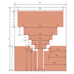
Figure 1 shows the configuration of the novel antenna. It was printed on low-cost FR-4 microwave substrate measuring 32 x 26 mm and featuring 1-mm thickness, with relative dielectric constant of 4.4. The antenna features two rectangular ground planes. The CPW feed line is designed by using a rectangular patch to connect with the stepped-gradient-structure patch of the main radiator. Both patch structures are printed on the same side of the FR-4 substrate. The CPW feed line is designed for a characteristic impedance of 50 Ω with fixed 2.8 mm (W10 = 2.8 mm) feed line width and 0.3-mm ground gap. The antenna provides a wide bandwidth with omnidirectional radiation pattern. Optimal dimensions for the antenna are as follows:
L = 32 mm;
L1 = 8.0 mm;
L2 = 4.0 mm;
L3 = 2.5 mm;
L4 = 2.5 mm;
L5 = 2.0 mm;
L6 = 11.0 mm;
L7 = 10.0 mm;
L8 = 11.25 mm;
L9 = 12.5 mm;
W = 26.0 mm;
W1 = 23.0 mm;
W2 = 17.0 mm;
W3 = 12.0 mm;
W4 = 9.0 mm;
W5 = 6.0 mm;
W6 = 10.0 mm;
W7 = 8.0 mm;
W8 = 9.0 mm;
W9 = 11.3 mm; and
W10 = 2.8 mm.
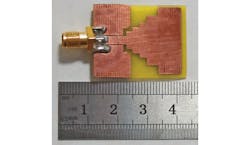
Figure 2 shows a prototype of the antenna, fabricated by hand and based on the optimal dimensions. The antenna design was analyzed by changing one parameter at a time with all other parameters fixed. A commercial simulation software was used for the analysis: the High Frequency Structure Simulator (HFSS) from Ansoft. Figure 1 shows the dimensions for the antenna as a result of this optimization approach. The antenna appearing in Fig. 2 was fabricated to verify the design.
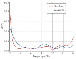
The antenna’s impedance bandwidth was simulated with HFSS and measured for the prototype using a model 37269C vector network analyzer (VNA) from Anritsu Co. The results for the simulation and measurements are shown in Fig. 3, with close agreement between the sets of data. Discrepancies between simulated and measured results are likely caused by measurement environmental effects, SMA connector effects, fabrication imperfections, and inappropriate quality of the microwave substrate, not all of which were included in the simulations. The results show an impedance bandwidth of 3.1 to 13.5 GHz for the antenna, or more than 10 GHz for a voltage standing wave ratio (VSWR) of less than 2.0:1. It is clear that the antenna can be used for frequencies above the FCC band in various applications.
This file type includes high resolution graphics and schematics when applicable.
Radiation Revelations
This file type includes high resolution graphics and schematics when applicable.
Related Articles
• UWB RFID System Cuts Coupling By 20 dB
• UWB Antenna Blocks Interference
• Low-Power Mixer Converts UWB Signals
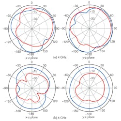
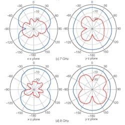
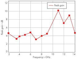
To study the antenna’s radiation patterns, two principle planes were selected. These are referred to as the x-z plane (H-plane) and the y-z plane (E-plane). Figures 4(a) through (d) show the normalized radiation patterns in the H- and E-planes for the antenna at 4, 6, 7, and 8 GHz, respectively. The results reveal that the antenna provides an acceptable quasi-omnidirectional radiation pattern suitable for receiving signals from all directions at lower frequencies. Due to antenna surface currents, however, its cross-polarization performance deteriorates with increasing frequency. Figure 5 plots the antenna’s measured peak gain as a function of operating frequency. Gain ranges from 3.3 to 10.1 dB in the measurement range from 2 to 14 GHz; gain across the full impedance bandwidth of 3.1 to 13.5 GHz always exceeds 3 dB, indicating that the antenna design is suitable for use in UWB systems.
In short, this compact monopole microstrip antenna shows promise for UWB applications. Following simulations with HFSS software, a prototype measuring just 32 x 26 mm was fabricated on FR-4 substrate. Simulations and measurements show an impedance bandwidth of 3.1 to 13.5 GHz, a bandwidth of more than 10 GHz for a VSWR of less than 2.0:1. The antenna has an acceptable quasi-omnidirectional radiation pattern required to receive information signals from all directions at lower frequencies. It is thus an attractive candidate for UWB communications applications.
Bo Gao, Lecturer
College of Communication Engineering, Jilin University, Changchun 130012, Jilin Province, People’s Republic of China.
Ge Wu, Engineer
College of Electronic Science and Engineering, Jilin University, Changchun 130012, Jilin Province, People’s Republic of China.
Jia-Yu Huo, Doctoral Student
College of Communication Engineering, Jilin University, Changchun 130012, Jilin Province, People’s Republic of China.
Xiao-Jian Tin, Professor
College of Electronic Science and Engineering, Jilin University, Changchun 130012, Jilin Province, People’s Republic of China.
Acknowledgments
This work was supported in part by the National Natural Science Foundation of China under Grant No. 60372061, and the Changchun Science and Technology Support Program under Grant No.11KZ36.
References
1. W. T. Li, Y. Q. Hei, W. Feng, and X. W. Shi, “Planar Antenna for 3G/Bluetooth/WiMAX and UWB Applications With Dual Band-Notched Characteristics,” IEEE Antennas & Wireless Propagation Letters,Vol. 11, 2012, pp. 61-64.
2. H. Yoshioka, L. Yang, E. Tammam, and K. Yoshitomi, “A Highly Compact Dual-band WLAN/UWB Monopole Antenna,” IEICE Electronic Express, Vol. 9, No. 3, 2012, pp. 160-164.
3. M. Jusoh, M.F. Jamlos, M.R. Kamarudin, and F. Malek, “MIMO Antenna Design Challenges for UWB Applications,” Progress in Electromagnetic Resonances, Vol. 36, 2012, pp. 357-371.
4. Z.Y. Li, Q. Zhang, H.L. Wang, X. Luo, and Y.L. Liu, “A Novel Miniature UWB Microstrip-fed Antenna With L-Shape Ground,” Proceedings of ISPACS, Chengdu, China, December 6-8, 2010.
5. M. Abdollahvand, G. Dadashzadel, and D. Mostafa, “Compact Dual Band-Notched Printed Monopole Antenna for UWB Applications,” IEEE Antennas & Wireless Propagation Letters, Vol. 9, 2010, pp. 1148-1151.
6. R.A. Kumar, Y.K. Choukiker, and S.K. Behera, “Design of Hybrid Fractal Antenna for UWB Application,” in Proceedings of the ICCEET, March 2012, pp. 691-693.
7. S. Mohammadi, J. Nourinia, C. Ghobadi, and M Majidzadeh, “A Novel Compact CPW-Fed Slot Antenna With A Pair of Parasitic Patches for UWB Applications,” Proceedings of the 20th ICEE, Tehran, Iran, May 15-17, 2012, pp. 1409-1413.
8. Y.S. Li, W.X. Li, and Q.B. Ye, “A Reconfigurable Wide Slot Antenna Integrated With SIRS for UWB/Multiband Communication Applications,” Microwave & Optical Technology Letters, Vol. 55, No. 1, January 2013, pp. 52-55.
9. C. Deng and Y.J. Xie, “Dual Band-Notched Design of Rectangular Monopole Antenna for UWB Applications,” Progress in Electromagnetic Resonances, Vol. 14, 2010, pp. 213-225.
10. M. Naser-Moghadasi, R. Hafezifard, R.A. Sadeghzadeh, H. Seyyedhatami, and M. Torkamani, “Small Circular-Shaped UWB Antenna for Wireless Communication Applications,” Microwave & Optical Technology Letters, Vol. 54, No. 12, December 2012, pp. 2885-2888.
11. M. Moosazadel, C. Ghobada, and M. Dousti, “Small Monopole Antenna With Checkered-Shaped Patch for UWB Application,” IEEE Antennas & Wireless Propagation Letters, Vol. 9, 2010, pp. 1014-1017.
12. T. Li, H.Q. Zhai, G.H. Li, L. Li, and C.H. Liang, “Compact UWB Band-Notched Antenna Design Using Interdigital Capacitance Loading Loop Resonator,” IEEE Antennas & Wireless Propagation Letters, Vol. 11, 2012, pp. 724-727.
13. K Mohammadpour-Aghdam, S Radiom, R Faraji-Dana, A. E. Vandenbosch, and G. E. Gielen, “Miniaturized RFID/UWB Antenna Structure that Can be Optimized for Arbitrary Input Impedance,” IEEE Antennas & Propagation M, Vol. 54, No. 2, April 2012, pp. 75-87.
This file type includes high resolution graphics and schematics when applicable.
