Antenna Aims At Dual Bands

Wireless applications continue to spread across different bandwidths, with wireless local area networks (WLANs) alone occupying several frequency bands. To realize effective antenna designs for these applications, it is possible to use a modified ground structure (MGS) to achieve dual-band operation. To form the MGS, a rectangular ground plane is shorted with dual meandered side strips and dual tapering protruding stubs. Prototype antennas based on this design approach show dual operating bands centered at 2.4 and 5.5 GHz, with reflection coefficients (|S11|) of better than -10 dB and frequency coverage for 2.4-, 5.2-, and 5.8-GHz WLAN standards. In addition, antenna designs using the MGS have achieved stable monopole-like radiation patterns and acceptable gain across the three WLAN operating bands.
Antennas are critical components in WLAN and other wireless systems. In the quest for designs that offered low profiles, light weight, low cost, and ease of integration with other circuits, planar printed antennas were extensively investigated. More recently, monopole antenna designs have been considered for these wireless applications, including a design with a G-shaped construction,1 a double T-shaped design,2 an antenna created by adding parasitic elements,3 and a slotted monopole version.4,5 These different approaches can provide two or three current paths to excite multiple resonant modes for multiple-frequency operation, although the majority of the design efforts have been on monopole structures. The use of MGS approaches is attractive because it has been widely employed in the form of defected ground structures (DGS) in many different microwave and wireless components.6-9
Reference 6, for example, details the use of a cross-shaped DGS to broaden the operating bandwidth and reduce the size of a conventional DC bias line. Dumbbell-shaped DGS shapes were applied under the feed line to suppress harmonics in the bandpass filter design of ref. 7. A DGS with U-shaped slot helped obtain a notched band to avoid interference in an ultrawideband (UWB) power divider in ref. 8 and an UWB antenna in ref. 9.
In multiband antenna design, the MGS is also a simple and effective way to excite additional resonance modes, such as a rectangular ground with dual inverted L-shaped strips,10 a cambered ground plane with an isosceles-triangle-shaped defect,11 and an L-shaped slot cut out of the ground.12 However, multiband performance relies on the hybrid combination of MGS and traditional monopole technologies: The MGS introduces a single resonance, with the other resonant modes excited by the traditional monopole antenna.
Figure 1 shows the geometry of the proposed dual-band antenna and its modified ground plane. The antenna is etched on the laminated sides of a 1-mm-thick FR-4 printed-circuit-board (PCB) substrate, which features relative dielectric constant of 4.6 and measures just 20 x 28 mm. Unlike a conventional microstrip-fed antenna with a solid ground plane, this design features a ground plane that was modified to form an MGS. Dual meandered side strips, with total length of L4 + W4 + L5 + W5 (which is about one-quarter wavelength at 2.4 GHz), are etched on the edge of the substrate to connect with the rectangular ground plane, achieving a resonance at 2.4 GHz in a relatively limited space.

1. These diagrams show top, side, and bottom views of the proposed dual-band MGS antenna.
The ground plane’s left and right sides protrude with dual tapering stubs of height L3, providing another current path and achieving an additional resonant mode with good impedance bandwidth at around 5.5 GHz. The MGS is electromagnetically fed by a 50-Ω microstrip feed line, placed on the center of the antenna PCB. For improved lower-frequency impedance matching, the microstrip feedline is protruded with a thin line stub from the line’s upper side.
A commercial electromagnetic (EM) computer-aided-engineering (CAE) software package was used for numerical analysis to examine the performance of the proposed antenna design. The software, the High-Frequency Structure Simulator (HFSS) from Ansoft, is based on finite-element-method (FEM) analysis. Via iterative trials, the final optimal dimensional values for the antenna were obtained and are listed in the table.
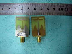
2. This photograph shows top (left) and bottom (right) views of the fabricated prototype MGS antenna.
A prototype of the proposed antenna was experimentally fabricated and measured to support the EM simulation, and a 50-Ω SMA connector was used to feed the antenna, as shown in Fig. 2. The simulated and measured reflection coefficient magnitudes (|S11|) of the proposed dual-band antenna based on MGS are illustrated in Fig. 3. As Fig. 3 shows, the proposed antenna achieves dual-resonant modes over the frequency ranges of 2.40 to 2.52 GHz and 4.95 to 6.01 GHz for |S11| ≤ -10 dB, simultaneously covering the 2.4-, 5.2-, and 5.8-GHz WLAN frequency bands. The values from the simulations agreed closely with the measured results for the antenna. Some slight discrepancies may be attributed to the presence of the SMA feed connector and soldering the connector onto the antenna PCB, design elements that were not included in the simulation.

3. These plots show the simulated and measured |S11| performance for the proposed MGS antenna as a function of frequency.
Figure 4 plots the frequency response of |S11| for the proposed antenna. As can be seen, for the case with dual side strips on the ground (ant 2), the lower-band resonance was effectively excited. The upper-band resonance matching conditions were obtained when dual protruding stubs were shorted to ground (ant 3). These results clearly suggest that the dual side strips and dual protruding stubs can significantly affect the impedance matching of the lower and upper resonance bands. To achieve the bandwidth enhancement in the upper resonance band, the protruding stubs were tapered (ant 1) instead of rectangular. As Fig. 4 shows, the impedance matching for the lower resonance band is degraded when the feed line is a uniform width without a thin stub (ant 4).

4. These plots show the differences in S11 performance for the proposed antenna with four different modifications to the ground structure (ant 1, 2, 3, and 4).
Figure 5 shows the excited current distributions obtained from HFSS simulations, both for the feed line and the ground for the optimized antenna. As expected, strong surface current densities were present at the lower and upper resonance bands along the dual side strips and protruding stubs, respectively.

5. The surface current distributions on the novel MGS antenna are shown here at (a) 2.44 GHz, (b) 5.2 GHz, and (c) 5.8 GHz.
According to the current distributions and frequency responses for |S11| in these different cases, a number of parameters were investigated for their effects on the resonant frequency bands of interest. Figure 6 shows the tuning effect of length L5, with selected values from 7.2 to 8.8 mm, on the response of |S11|. As can be seen, the lower band resonance is significantly impacted and shifted downward in frequency with increasing values of tuning length, while the upper band remains almost unchanged. The main reason for this is that for larger L5 values, the longer dual side strips approximate one-quarter wavelength at the relevant resonant frequency and vice versa. Similarly, changing the tapering stub length, L3, has impact on the upper resonant-frequency band; thus, the upper resonance can be tuned by adjusting the values L3, as shown in Fig. 7.

6. The impact of changing the strip length, L5, on |S11| performance is shown here.

7. The impact of changing slot length, L3, on |S11| performance is shown here.
Figure 8 shows three-dimensional (3D) radiation patterns obtained from EM simulations at 2.44, 5.20, and 5.80 GHz. The symmetrical structure of the antenna design yields symmetrical and consistent radiation patterns, which are ideal for a multiband communications antenna. Figure 8 also shows two-dimensional (2D) radiation patterns in the main cut planes of the antenna. As can be seen, the antenna yields nearly monopole-like radiation performance with conical patterns in the elevation planes and omnidirectional patterns in the azimuth plane. As Fig. 9 shows, the peak gains in the operating bands of interest are stable and reasonable.

8. Radiation patterns for the three frequencies of interest are shown for the MGS antenna in 3D (top) and 2D (bottom) plots.

9. These plots show the variations in peak gain in the 2- and 5-GHz frequency bands.
In conclusion, the microstrip-fed antenna with MGS achieves quite acceptable performance in a small physical PCB format. Unlike an antenna with a conventional solid ground plane, the ground for this novel antenna is modified with dual meandered side strips and dual tapering protruding stubs. The feed line is also simply modified for enhanced impedance-matching performance. The antenna design exhibits monopole-like radiation pattern and acceptable peak gains across the operation bands.
Feng-Chao Ren, Doctor
Fu-Shun Zhang, Doctor
Jian-Hui Bao, Doctor
Qiu-Yan Zhou, Researcher
Yong-Chang Jiao, Researcher
Key Laboratory of Antennas and Microwave Technology, Xidian University,
Xi’an, Shaanxi 710071, China; e-mail: [email protected].
References
1. Yue Song, Yong-Cang Jiao, Hui Zhao, Zheng Zhang, Zi-Bin Weng, and Fu-Shun Zhang, “Compact printed monopole antenna for multiband applications,” Microwave and Optical Technology Letters, Vol. 50, No. 2, 2008, pp. 365-367.
2. Yen-Liang Kuo and Kin-Lu Wong, “Printed double-T monopole antenna for 2.4/5.2 GHz dual-band WLAN operations,” IEEE Transactions on Antennas & Propagation, Vol. 51, No. 9, 2003, pp. 2187-2192.
3. P. Xu, Z.-H. Yan, and C. Wang, “Multi-band modified fork-shaped monopole antenna with dual L-shaped parasitic plane,” Electronics Letters, Vol. 47, No. 6, 2011, pp. 364-365.
4. Wen-Chung Liu, Chao-Ming Wu, and Nien-Chang Chu, “A compact CPW-fed slotted patch antenna for dual-band operation,” IEEE Antennas & Wireless Propagation Letters, Vol. 3, 2010, pp. 110-113.
5. Chih-Yu Huang and En-Zo Yu, “A slot-monopole antenna for dual-band WLAN applications,” IEEE Antennas & Wireless Propagation Letters, Vol. 10, 2011, pp. 500-502.
6. J. Ma, T, Jing, and Y.-Z. Yin, “Compact and wideband DC bias line based on defected ground structure,” Journal of Electromagnetic Waves and Applications, Vol. 24, 2010, pp. 435-443.
7. Y.C. Guo, L.H. Weng, and X.W. Shi, “An improved microstrip open-loop resonator bandpass filter with DGSS for WLAN application,” Journal of Electromagnetic Waves and Applications, Vol. 23, 2009, pp. 463-472.
8. Z. Zhang, Y.-C. Jiao, Y. Song, H.-H. Xie, S. Tu, and F.-S. Zhang, “A compact 1 to 2 Wilkinson power divider for 2.4-GHz/UWB with band-notched characteristic using simple defected ground structure,” Journal of Electromagnetic Waves and Applications, Vol. 23, 2009, pp. 1623-1630.
9. K. Yin and J. P. Xu, “Compact ultra-wideband antenna with dual bandstop characteristic,” Electronics Letters, Vol. 44, No. 7, 2008, pp. 453-454.
10. Wen-Chung Liu, Chao-Ming Wu, and Yang Dai, “Design of triple-frequency microstrip-fed monopole antenna using defected ground structure,” IEEE Transactions on Antennas & Propagation, Vol. 59, No. 7, 2011, pp. 2457-2463.
11. Jing Pei, An-Guo Wang, Shun Gao, and Wen Leng, “Miniaturized triple-band antenna with a defected ground plane for WLAN/WiMAX applications,” IEEE Antennas & Wireless Propagation Letters, Vol. 10, 2011, pp. 298-301.
12. Macro A. Antoniades and George V. Eleftheriades, “A compact multiband monopole antenna with a defected ground plane,” IEEE Antennas & Wireless Propagation Letters, Vol. 7, 2008, pp. 652-655.
