Keeping Power Levels In Check
Power levels often must be maintained and monitored in RF/microwave systems, and those tasks can depend on simple-but-important passive components: directional couplers and power dividers/combiners. They are available in a variety of package styles—including compact surface-mount housings, coaxial packages, and even waveguide housings—with many different frequency ranges, from high-frequency (HF) bands through millimeter-wave frequencies. Suppliers for these components number many; a fundamental knowledge of essential mechanical and electrical characteristics for each component type can help simplify the specification process.
Directional couplers are often used to measure power levels or to monitor signals by tapping off or sampling a small amount of the main signal. It is known as a “directional” coupler since this component can separate and sample signal components based on the direction of signal flow. By placing signal transmission paths close enough in a directional coupler’s circuitry, part of the signal from the main-line transmission path can be transferred to a coupled path and made available at a coupled output port. The coupling ratio is the difference between the power level of the main-line signal at its output port and the power level of the coupled signal, or:
Coupling ratio = 10log(Pout of the coupled path/Pin)
where:
Pout = the output signal power and
Pin = the input signal power.
Directional couplers are available commercially with different coupling factors or ratios, such as 10, 20, and 30 dB. A 30-dB coupler will provide 30 dB of the input power at its coupled port, or about a factor of 0.001 of the input power at the coupled port. For high-power levels, this is a convenient means of providing a lower-level signal for analysis with a sensitive power meter. Very high-power measurements may even call for a directional coupler with coupling factor as high as 40 dB.
Along with its frequency range and coupling factor, RF/microwave directional couplers can be differentiated by a number of performance parameters, including directivity, loss, VSWR, and maximum input power rating. Directivity, which is a measure (in dB) of how well the component isolates forward and reverse (or reflected) signals, is critical when a directional coupler will be used to measure return-loss levels. Directional couplers with high directivity enable high measurement accuracy when using that coupler in a test system for forward or reflected power measurements.
A directional coupler’s voltage standing wave ratio (VSWR) provides an indication of how closely the component is matched to its designed characteristic impedance; this is typically 50 Ω but can be 75 Ω in video and cable-television (CATV) transmission systems. Low VSWR is to be preferred, and using a directional coupler with low VSWR is a way to minimize impedance mismatch errors and to improve power measurement accuracy.
Loss through a coupler represents the amount of signal power that is attenuated due to power dissipated through coaxial connectors, printed-circuit boards (PCBs), and resistive circuit elements. Depending upon the manufacturer, a directional coupler’s loss may be defined as insertion loss, which is separate from coupling losses, or as transmission loss, which combines insertion and coupling losses. As with VSWR, lower values are to be preferred, since they mean that more of the input power to a directional coupler will be preserved at its output ports.
The maximum input power rating of a directional coupler is often dependent on the coupler’s package style, with small surface-mount housings offering the lowest input power ratings because of the small size. Couplers with coaxial connectors are limited in power-handling capabilities to some degree by the connectors, with SMA connectors typically handling about 50 W CW power.
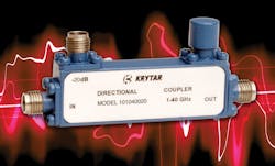
As an example of how the key performance parameters appear for a commercial directional coupler, model 101040020 from Krytar is a recently introduced coaxial directional coupler with extremely broadband frequency coverage from 1 to 40 GHz using stripline circuitry and SMA coaxial connectors (see figure). It has a nominal coupling value of 20 dB across that frequency range and serves a variety of commercial and military applications, including signal monitoring and measurement, antenna beam forming, and electromagnetic-compatibility (EMC) testing. The 20-dB coupling is flat within a ±1-dB window, while the insertion loss (not including coupling loss) is less than 0.85 dB from 1 to 20 GHz and less than 1.5 dB from 20 to 40 GHz. The directivity is higher than 14 dB from 1 to 20 GHz and higher than 10 dB from 20 to 40 GHz. The maximum VSWR at any port is 1.50:1 to 20 GHz and 1.70:1 to 40 GHz. The directional coupler is rated for maximum average input power of 20 W, but as much as 3 kW peak input power (short pulses).
Power dividers/combiners are often used to create multiple versions of a signal for a system or to combine multiple inputs into one signal for a system. Power dividers are usually designed so that an equal amount of the input power is distributed to the output ports. In a two-way power divider, one-half of the input power is available at each output port; in a four-way power divider, 25% of the input power is available at each output port; and so on.
An ideal two-way power divider would provide two output signals at precisely one-half the power level as the input signal. In the real world, however, a power divider suffers some amount of insertion loss, along with other forms of loss (such as return loss from reflections, and impedance mismatches at connections to and from the power divider). And real power dividers/combiners are sometimes designed with as many as 64 output ports.
The performance of these components is described by similar parameters as for directional couplers, such as insertion loss and VSWR. In addition, ports are characterized by the amount of isolation between them, the amplitude balance (or imbalance) between ports, and the phase balance (or imbalance) between ports. Power dividers/combiners come in many forms, including as quadrature (90-deg.) and 180-deg. hybrid couplers. A quadrature hybrid splits an input signal into two output signals, each at one-half or 3 dB the power level and offset 90 deg. in phase. A 180-deg. hybrid splits an input signal into two equal-amplitude output signals that are offset 180 deg. in phase.
Although many of the basic design concepts behind directional couplers and power dividers/combiners have changed little in several decades, increased attention is being paid to newer parameters—such as passive intermodulation (PIM)—which can impact how these components perform in modern communications systems. Systems using digital modulation formats, for example, require couplers and power dividers/combiners with minimal levels of PIM.
Designers of these components are also exploring the value of different building-block materials, such as low-temperature-cofired-ceramic (LTCC) circuit substrate materials. These materials feature excellent thermal conductivity characteristics for handling high power levels and high operating temperatures compared to conventional PCB materials.
Suppliers of directional couplers, hybrids, and power dividers/combiners offer products in many different package styles, including miniature drop-in and surface-mount housings, coaxial packages, and high-power waveguide enclosures. Suppliers include ARRA, Bird Technologies, Connecticut Microwave, Fairview Microwave, Innovative Power Products, JFW Industries, Krytar, M/A-COM, MCLI, Meca, Marki Microwave, Mini-Circuits, MITEQ, Narda East, Pasternack, PMI, Pulsar Microwave, Skyworks Solutions, Synergy Microwave Corp., TRM Microwave, and Werlatone. The most complete listings for these products can be found online at the Microwaves & RF Product Data Directory.
For those seeking fundamental background information on directional couplers and power dividers, an excellent eight-page white paper, “Microwave Power Dividers and Couplers Tutorial,” is available free of charge from Marki Microwave. In addition, Mini-Circuits offers a free application note, “Directional Couplers,” which explains the use of these passive components for test and systems applications.
About the Author
Jack Browne
Technical Contributor
Jack Browne, Technical Contributor, has worked in technical publishing for over 30 years. He managed the content and production of three technical journals while at the American Institute of Physics, including Medical Physics and the Journal of Vacuum Science & Technology. He has been a Publisher and Editor for Penton Media, started the firm’s Wireless Symposium & Exhibition trade show in 1993, and currently serves as Technical Contributor for that company's Microwaves & RF magazine. Browne, who holds a BS in Mathematics from City College of New York and BA degrees in English and Philosophy from Fordham University, is a member of the IEEE.
