New Modulation Schemes Raise PIM
This file type includes high resolution graphics and schematics when applicable.
Consumers and industrial users are demanding higher rates of wireless connectivity and uninterrupted connections. This would imply the need for a very complex system of transmitters and receivers distributed throughout common environments and in industrial facilities. Such demands require transceiver systems with very high throughput capability across many different frequency bands. The latest modulation standards, such as LTE-Advanced (LTE-A) and WiGig, are designed to meet these demands in the busiest of thoroughfares or facilities.
In the meantime, however, the legacy challenge of dealing with modulation distortions caused by passive components has increased wireless system costs, decreased system performance, and raised the standards of component construction. Passive-intermodulation (PIM) distortions decay data rates, block frequency bands, and are highly costly to pinpoint and repair. Distributed antenna systems (DAS) and small cells are more susceptible to PIM interference that large stand-alone antenna systems. Understanding PIM’s broad-spectrum effects and developing best practices to guard against, may become a necessity for complex antenna systems.
By definition, passive-intermodulation distortion is a complex frequency response that occurs when multiple frequency tones exist along the same signal path and encounter nonlinear junctions. PIM differs from the harmonic products of mixing, as they are usually closer to the frequency band of reception. Modulation-distortion products are a known problem with active nonlinear devices like mixers, circulators, and amplifiers. These components are rigorously designed to limit their distortion products.
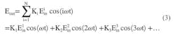
The material properties of structures used in the construction of RF/microwave components also can produce nonlinear effects at certain frequencies and under certain conditions. When these nonlinear junctions are present in the signal path of an RF/microwave signal, the signals combine and produce PIM. Mathematically, PIM can be explained using a power series with sinusoidal signals. Eq. 1 is a power series of an amplitude product and an electric signal.

The output of such a power series is a simple solution, as indicated in Eq. 2.

When a single sinusoidal signal is added to the input of the system, more complex products are produced. The expansion in Eq. 3 demonstrates a harmonic response that grows in frequency as integer multiples of the input sinusoidal signal frequency.
The input signal in Eq. 4 is a compound signal of two sinusoidal tones.

When two tones are input into a power series, the response is a progression of multiple-order products. This progression is shown in Eq. 5 with only the odd-order products up to the ninth order. The order is determined by the addition of the integers multiplied by the frequency. The amplitude of the signal also is a function of the progression, and decreases as the order increases.
In Eq. 5, for example, the integer multiplied by frequency one is 2. The integer multiplied by frequency two is 1. The combination of these two integers is the designation for the third-order intermodulation distortion . These products occur at the combination frequencies and at various power levels. For two tones, the frequencies at which these products occur is dictated by Eq. 6, where m is 1 less than n (Table 1).


The power of these unintended signals decreases as the order of the product increases. This is represented mathematically in Eq. 7.

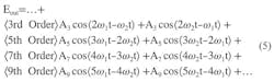
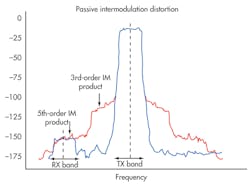
Graphically, this appears as a series of impulses at the frequency combinations (Fig. 1). The third-order product is often the product of concern, as it could potentially be of high enough power and within the reception band. This product also could increase the noise floor in the reception band and lower the signal-to-noise ratio (SNR). In doing so, it will directly degrade the throughput performance of high-speed data lines.
This file type includes high resolution graphics and schematics when applicable.
Pinpointing The Problem
This file type includes high resolution graphics and schematics when applicable.
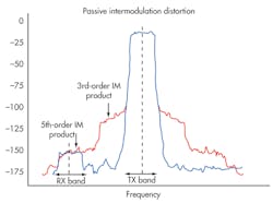
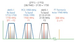
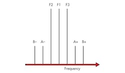
As most signals broadcast from telecommunication antennas are not perfect tones, the PIM and harmonic responses are not impulses. The responses are spread more widely through the frequency spectrum (Fig. 2). This aspect suggests that the PIM product doesn’t need to be exactly within the reception band to cause distortions. Rather, it must be within the receive filter’s passband (Fig. 3).
As the LTE and LTE-A standards require higher-throughput data, maintaining a low noise floor is a chief concern. Telecommunications systems in less dense spectrum may only consider third-order intermodulation distortion as significant. This is not the case with very dense spectrum, as the other-order products could be within the reception band of neighboring carriers. Other-order products also may increase the noise floor throughout the system, as they may be retransmitted.
Commonly used cellular telecommunications bands are affected by PIM products beyond just third-order intermodulation distortion. The antenna front ends and antennas for these complex digital modulation standards also are increasing in frequency performance and density. For example, increased frequency-handling capability is being designed into the latest mobile antennas. These antennas transmit and receive efficiently at many different bands and switch between these bands rapidly.
This approach would not cause enhanced PIM issues in an isolated system. When these antenna systems are distributed throughout an environment to ensure good signal reception, the proximity of these antennas decreases. This densification of antennas and broadcast frequencies has led to a scenario in which the redundant transmission of the antennas could induce significant PIM levels within their companion structures. PIM then extends beyond the simple two-tone frequency case and multiplies the frequencies mixing throughout the signal environment (Fig. 4).
The products for multi-tone frequency mixing are more numerous than with just two tones. In a two-tone mixing, there are only two third-order intermodulation-distortion odd-order products that are considered of primary concern. With three-tone, mixing there are four third-order intermodulation-distortion odd-order products of similar power levels (Table 2). Modulation schemes that use the same frequency for transmit and receive (like time-domain LTE and WiGig, for example) could exhibit degraded performance with multi-tone PIM generators nearby.

This problem is compounded when considering distributed antenna systems (DASs). DASs are predominantly used for commercial and industrial areas, where enclosed spaces limit larger cell broadcasting. These areas are often more prone to having PIM generators in the environment and near the antennas. PIM generators could be any material that is electrically responsive in the environment—with either nonlinear properties or the potential for such properties when in contact with other materials.
This file type includes high resolution graphics and schematics when applicable.
Pursuing Low-PIM Performance
This file type includes high resolution graphics and schematics when applicable.
PIM generators include ferromagnetic materials, galvanic contacts, solder joints, screw connections, conductive coatings, rust, and antenna systems. Such concerns have driven manufacturers of RF/microwave passive components to design low PIM-performing products. Low-PIM construction requirements involve carefully designing every interconnection between components for low PIM and choosing materials that possess very low PIM.
Low-PIM parts like adapters, couplers, splitters, attenuators, switches, cables, and antennas are common. Designing for PIM can be a costly design process and expensive to implement. Generally, using low-PIM components does not ensure that a telecommunications site will be resilient to PIM.
External PIM generators as well as improper installation can be a large factor in producing PIM. Highly cluttered environments in particular are troubling for DAS and small-cell installations. Certain antenna designs, such as omni-directional antennas, could suffer from PIM without the ability to remove offenders from the environment. These factors have created an attractive market for quasi-omnidirectional antennas. Such antennas are composed of several highly directional, offset-radiating elements combined to form an envelope response that is similar, but not omni-directional.
With a common three-lobe structure indicative of such antennas, the system can be rotated to position a PIM generator in a null zone between lobes. This option still offers reasonable coverage in null zones for mobile devices, as the compound reflections could provide adequate reception. Scenarios like these make quasi-omnidirectional antennas a potential PIM fighting solution for fixed small-cell locations like telephone poles, street lights, power lines, and building edges.
Generally, DAS antennas have limited freedom for positioning. But a few tens of centimeters of location change could enable significantly lower PIM response. Some installers will do a PIM sweep when they install the DAS antennas and use an antenna on a movable pole to sense for the lowest PIM position. A technique like repositioning is effective with lower-power antennas, as PIM generators further from the antenna reflect less power and the separation distance grows. Clever methods, like this PIM spotting, may be essential for DAS installations for services like LTE-A and WiGig.
As of September 2013, a report by Network Digest noted that 1064 LTE mobile devices had been announced by 111 different manufacturers. This represents approximately 150% annual growth. Also, the Global Mobile Suppliers Association predicted that 260 commercial LTE networks in 93 countries would be in operation by the end of 2013. The network density needed to support the predicted traffic volume will only add to the requirements for PIM-driven design.
To enable LTE-A’s and WiGig’s high data rates, for example, the resistance of the modulation methods to noise and distortions has been compromised. Another factor to consider is the enhanced sensitivity and broader-band operation necessary for receivers in high-throughput services. Other methods to increase data rates proposed for LTE-A, such as carrier aggregation (CA), further weaken the service to PIM-based distortions.
CA is a proposed addition to the LTE-A standard that allows for multiple carrier reception. This method would increase the apparent throughput of data to the device. Yet this approach becomes another PIM concern, as several powerful antennas would need to broadcast in a single area and on different frequency bands to enable operation.
If a location had any PIM generators in the vicinity, it could potentially induce PIM responses to several of the transmitted signals. This would significantly hamper uplink data rates and could potentially disable the ability of one or multiple carriers to receive. To avoid this, a concerted effort from the installers and maintainers of these telecommunications systems would need to be arranged.
The goal of this effort would be to limit intersystem PIM production. This may be an impossible effort to undergo, as many system installers would be adding new systems or revamping old systems throughout an area. Different service providers also may be operating within the same area. As there is no standard for PIM maximums for external devices (and only for the maximum power output of transmitters), inter-site interference may become a significant issue. Such scenarios call for the development of an inclusive and extensive PIM standard.
The International Electro-technical Commission (IEC) developed a PIM testing standard in 1999, choosing two 20-W carriers with 5-kHz bandwidth as the standard for measuring PIM response. Additionally, third-order intermodulation distortion is designated the qualifying product for PIM response for mobile applications. The IEC produced an update to its standard in 2012, describing in more detail the process in which antennas, cables, connectors, filters, and assemblies would be tested (including dynamic testing). Considering the rapidly changing technologies, however, this standard may not prove adequate for PIM responses for many applications.
Applications that may require more stringent PIM maximums and testing procedures include those that use higher carrier power or where multiple carriers are operating, the bandwidth of the carrier is greater than 5 kHz, and intermodulation products may be of concern. The standard’s testing protocol also omits reasonable descriptions for vibration, wear and tear, installation error, temperature, and materials. Sweeping signal frequencies is another test typology that may reveal PIM, which might not be as easily identified under standard two-tone tests. An additional consideration is three-or-more tone testing for dense signal environments.
As the frequency spectrum is filled with greater traffic and data demands drive up transmitter and carrier densities, PIM-induced system degradation is of increasing concern. A system composed of low-PIM-designed components may not ensure a low-PIM final installation. DAS and small-cell systems may also be more prone to PIM losses, as the necessary receiver sensitivity makes them less resilient to the poor SNR caused by PIM. More detailed best practices for system design and installation—along with less forgiving PIM standards—may be an industry requirement in the near future to enable the latest wireless standards.
This file type includes high resolution graphics and schematics when applicable.
About the Author
Jean-Jacques DeLisle
Jean-Jacques graduated from the Rochester Institute of Technology, where he completed his Master of Science in Electrical Engineering. In his studies, Jean-Jacques focused on Control Systems Design, Mixed-Signal IC Design, and RF Design. His research focus was in smart-sensor platform design for RF connector applications for the telecommunications industry. During his research, Jean-Jacques developed a passion for the field of RF/microwaves and expanded his knowledge by doing R&D for the telecommunications industry.
