This file type includes high resolution graphics and schematics when applicable.
Attenuators and terminations are commonly-used components in high-frequency systems, used to adjust or absorb power, respectively. In many ways, the two types of components are similar, since they are both designed to stop RF/microwave power. Attenuators decrease some portion of the power, in fixed or variable amounts, while terminations stop power applied to them altogether.
Both types of components are available in various forms, from miniature chips to higher-power coaxial components and the highest-power waveguide assemblies. Both types of components play important roles in high-frequency circuits and systems, especially when high-power signals must be managed.
Attenuators and, in particular, high-power terminations are usually specified with size, weight, power-handling capability, and frequency range as essential parameters for comparison. Power-handling capability is generally a function of size, with the highest-power components occupying the greatest amount of volume in a design.
A termination is a one-port component meant to absorb all the power applied to it, while an attenuator is a two-port component that reduces the level of the power passing through it by a fixed or variable amount. Attenuators can reduce signal power by a fixed amount or can provide an adjustable range of attenuation. For the most part, adjustments are continuously variable or switched in discrete steps.
Terminations are typically connected at an unused port in a system, such as an unused port of a power divider that is splitting off signal power to other parts of the system. In addition, terminations are used when a passive component (such as a filter or a coupler) is being matched to 50 Ω for measurement purposes, as when testing for return loss or power-handling capability. Terminations used for establishing reference impedances at high power levels are usually referred to as dummy loads.
Matching an attenuator or termination to an application is a matter of understanding the main operating parameters and making the best choice of component for a particular set of requirements. Attenuators are available with fixed attenuation values for a particular frequency range or with a range of attenuation settings that can be set in steps or under continuously variable control.
Whether fixed or variable, attenuators can be compared in terms of bandwidth, attenuation flatness across the frequency range, insertion loss, return loss or VSWR, power-handling capability, operating temperature range, size, and weight. For more on the fundamental operating parameters of RF/microwave attenuators, see “Know When To Add Attenuation.”
Terminating Power
As with attenuators, terminations are available in many form factors. These include miniature chips, coaxial packages, and high-power waveguide components, generally with power ratings to match their sizes. Terminations are characterized by fewer parameters than attenuators, since they do not exhibit amplitude responses as a function of frequency. Rather, the frequency range of a termination is the span of frequencies over which it can maintain an impedance match with a system’s characteristic impedance—usually 50 Ω, but sometimes 75 Ω for broadcast applications or other impedances for specialized uses.
An important function of an RF/microwave termination, especially for high-power models, is its capability to dissipate heat. Any type of power-absorbing component, such as a termination, can dissipate heat by means of conduction, convection, or radiation. Conduction takes place by means of physical contact of different materials, such as a flange-mounted termination to a heat sink.
Conduction occurs when heat is dissipated as it moves from areas of higher energy to areas of lower energy. Convection is a dissipation of heat from a source by means of a flowing liquid (such as water) or a flowing gas (including air, as in fan-cooled terminations). Thermal radiation occurs when a source emits EM waves that carry the heat energy—e.g., infrared (IR) radiation, as used in space heaters.
Any resistive element, including attenuators and terminations, will generate heat that must be dissipated to minimize temperature-related stress and ensure the long-term reliability of a component, circuit, or system. For that reason, terminations are usually fabricated from or packaged in a material with high value of emissivity or heat radiation efficiency.
An ideal thermal radiator would have an emissivity value of 1. While no materials exhibit that thermal radiating efficiency, aluminum comes close, with an emissivity of 0.9. For that reason, aluminum is often used to construct extremely high-power terminations, dummy loads, and attenuators.
Terminations are somewhat simpler to specify than RF/microwave attenuators, since the primary goals of any termination are to establish a good match with the system characteristic impedance and to absorb and dissipate a certain amount of power. As for attenuators, the number of suppliers for high-frequency terminations is large, with package styles ranging from tiny chip terminations to much larger waveguide terminations. As noted, heat must be dissipated, so the power-handling capabilities of these different terminations are related to physical size and connections to surrounding circuitry.
For example, American Technical Ceramics, which supplies both attenuators and terminations, supplies circuit-board-mountable components but in different packages and with different power ratings. The firm’s leaded and surface-mount-technology terminations are well suited for densely packed PCBs. However, these tiny components cannot match the power-handling and thermal-management capabilities of slightly larger flange-mount terminations and their larger cross-sectional mounting connections for effective thermal dissipation.
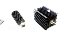
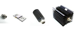
Res-Net Microwave builds its chip terminations and resistors on thermally dissipative beryllium oxide (BeO) substrate material, allowing for relatively large power-handling capabilities in small component sizes. The firm supplies terminations in most major package styles (see figure). These include conduction- and convection-cooled coaxial terminations with SMA connectors for use at power levels to 250 W from DC to 4 GHz, and the same power rating through 3 GHz with Type-N and TNC coaxial connectors.
The power-handling capabilities drop with increasing frequency, to about 50 W for SMA terminations operating to 18 GHz. The firm offers chip terminations based on its BeO substrates rated to 15 W at microwave frequencies.
Another material building block for high-power terminations is aluminum oxide, A2O3, also known as alumina, long a favorite substrate for high-power passive RF/microwave components. As an example, the chip resistors fabricated by US Microwaves on alumina substrates can also be used as chip terminations at power levels beyond 100 W through microwave frequencies.
The material supports a wide operating temperature range, from -65 to +200°C. Similarly, aluminum nitride material is effective for thermal dissipation, and is often used in packaging for high-power attenuators and terminations.
In spite of the thermal advantages of composite materials, higher power levels will require larger terminations to safely dissipate heat from a high-frequency design. Material advances have made possible some impressive power ratings for chip and SMT resistors, terminations, and attenuators. Nevertheless, higher-power applications, such as communications transmitters and radar systems, will still require the largest terminations and attenuators, usually with waveguide flanges for consistent dissipation of power levels that often exceed 1 kW CW.
This file type includes high resolution graphics and schematics when applicable.
About the Author
Jack Browne
Technical Contributor
Jack Browne, Technical Contributor, has worked in technical publishing for over 30 years. He managed the content and production of three technical journals while at the American Institute of Physics, including Medical Physics and the Journal of Vacuum Science & Technology. He has been a Publisher and Editor for Penton Media, started the firm’s Wireless Symposium & Exhibition trade show in 1993, and currently serves as Technical Contributor for that company's Microwaves & RF magazine. Browne, who holds a BS in Mathematics from City College of New York and BA degrees in English and Philosophy from Fordham University, is a member of the IEEE.
