Assemblies Combine Multiple Components
Microwave component manufacturers take many approaches to what are commonly known as integrated microwave assemblies (IMAs). Some tie analog components together exclusively, with others adding digital control, signal processing, and even microprocessors. But while the design philosophies applied to IMAs may vary, the intent of these multifunction modules is the same: to save space in a larger system. IMA designers typically achieve that goal with some clever architectures and packaging—in the process, shaving some of the real estate that would have been occupied by the separate components.
By their nature, most IMAs are custom designs, aimed at the needs of a specific system. For example: A system designer may need the multiple functions provided by a solid-state switch, switch driver, and filter bank, but is left with only open space for the size of a typical RF/microwave coaxial component. By integrating multiple functions into a common housing, microwave component designers can use internal switching, integrated circuits (ICs) instead of discrete components, and monolithic microwave integrated circuits (MMICs) instead of microwave integrated circuits (MICs). This allows them to fit three or more typical component functions into one package.
Design and manufacturing of IMAs typically requires broad expertise in a range of circuit technologies, circuit-board materials, and packaging approaches. Anaren (www.anaren.com), for example, cites its experience with many different circuit technologies. These include stripline, microstrip, and printed-wire board (PWB) circuits; soft and hard circuit substrate materials over a span of dielectric-constant values; and the skills to use the appropriate software design tools, including linear circuit simulators, electromagnetic (EM) simulators, and digital design tools. The firm has designed multilayer circuits on low-temperature-cofired-ceramic (LTCC) circuit materials, featuring as many as 30 circuit layers, to economize space in a system. The design and manufacturing capabilities are backed by a full complement of electrical and environmental test systems to fully evaluate multifunction designs. Anaren notes that typical prototyping cycles are only 12 wks.
Some IMA suppliers can best demonstrate their design and manufacturing skills by way of example. Aethercomm (www.aethercomm.com) shows its capabilities at achieving relative high transmit powers from a small volume. Its model TR 0.24-0.39-75 transmit/receive assembly measures just 3.70 x 8.125 x 1.00 in. with SMA connectors, but delivers transmitter output power to 100 W at frequencies from 290 to 390 MHz. It includes a receiver for use from 240 to 270 MHz with 18-dB gain and 3-dB noise figure. It is designed for use with nominal input power level of 2 W, but can handle a wide range of signal levels. The rugged unit is built for harsh environments, and is equipped with DC switching circuitry that enables and disables the transmitter and receiver functions in less than 10 µs. It can operate in both continuous-wave (CW) and pulsed signal modes, handling base-plate temperatures from -40 to +71°C. DC and logic connections are accessible via a DSUB connector.
Microwave Concepts (www.micro-con.com), a division of Micronetics, squeezes a number of X-band components in a hermetic phase control unit measuring just 2.35 x 1.50 x 0.38 in. with extended multipin connector. Model A228001-1 is a multifunction assembly that amplifies and divides a single X-band input signal into two phase-controlled output signals. The phase of the two output signals are independently controlled by means of both analog and digital phase shifters in each output channel. The digital phase shifters control a change of 180 deg. while the analog phase shifters control as much as 400 deg. Differential interfaces are used to control the output signal phase at high speed.
The assembly operates from 9.5 to 12.0 GHz and even provides 3 dB small-signal gain with gain flatness within 1.5 dB. The unit achieves better than 12 dB return loss with better than 5-deg. accuracy for the digital phase shifters. In addition, it has a 1-dB compression point of better than +10 dBm and draws 120 mA at +15 VDC and 20 mA at -15 VDC. It was designed for clock phase control in high-capacity data communication applications such as optical long-haul data networks.
TRAK Microwave Corp. (www.trak.com) specializes in combining switches and filters in compact assemblies for harsh environments. Model SWF002 is a prime illustration of that capability—a five-channel switched C-band filter assembly in a low-profile laser-welded hermetic housing for airborne use. The compact assembly includes a TTL driver for control. It incorporates five filter spaced 500 MHz apart, with stopband rejection of 60 dB ±500 MHz from the channel and passband insertion loss minimized to 6 to 10 dB. The switching speed from channel to channel is 100 ns or less while the maximum group delay in only 10 ns.
This is an extremely compact unit measuring just 2.29 x 1.40 x 0.265 in. and weighing only 0.8 oz. It uses hermetic SMP connectors and EMI filtered solder pins for DC connections, and handles RF power levels to +15 dBm. Power requirements are 80 mA at +5 VDC and 30 mA at -5 VDC. The switch filter assembly can handle operating temperatures from -54 to +85{DEG}C and has a rated mean time before failure (MTBF) of more than 350,000 hours.
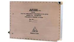
Akon (www.akonic.com) provides custom IMAs for ground-based and airborne applications, with numerous examples of its integration capabilities in standard designs such as the model A20-MH205 digital frequency discriminator (see figure). It covers 6 to 18 GHz and can process CW signals as well as pulses as narrow as 50 ns. It has a dynamic range of -63 to +7 dBm and 3 MHz RMS frequency accuracy. The externally triggered frequency discriminator provides 14-b resolution of measured frequency with fast 100-ns recovery time and only 200-ns shadow time. The broadband IMA draws 200 mA at +12 VDC, 1.3 A at +8 VDC, and 250 mA at -8 VDC. It operates at temperatures from -20 to +71°C. It measures 9.17 x 5.90 x 1.00 in. in aluminum housing.
K&L Microwave (www.klmicrowave.com) leverages its experience in filters to design and manufacture compact filter-based IMAs, including a TTL-controlled four-channel switched filter bank in a compact aluminum housing. As one would expect from K&L, the filter performance is outstanding. With four channels centered at 2975.0, 3132.5, 3332.5, and 3527.5 MHz, the maximum passband insertion loss is only 4 dB, with maximum amplitude ripple of only 0.4 dB. Phase deviation in any channel is within 1.5 deg. The out-of-band rejection for any of the channels ranges from a minimum of 50 dB to a maximum of 80 dB. The switching speed to select a channel under TTL control is less than 1 µs.
The firm has also developed the model 4SFB-00021 switched filter bank as an example of its integration capabilities. Designed for military and airborne applications, it handles center frequencies of 698, 730, 762, and 794 MHz using lumped-component filter designs and surface-mount component technology. Each channel provides 35-MHz bandwidth with passband insertion loss of 7.5-dB or less and out-of-band rejection of typically 60 dB. The IMA measures just 3.00 x 2.25 x 0.30 in. and can operate at altitudes to 10,000 ft. The switching speed from channel to channel is 300 ns.
MITEQ (www.miteq.com) has leveraged its successful component designs into more complex IMAs, typically for applications in satellite communications (satcom). Because weight and size are so critical in such systems, many of MITEQ’s designs attempt to integrate multiple subsystems within a single package. Among these is the model 131724 frequency downconverter, which covers three separate bands in an aluminum housing measuring 5.58 x 2.850 x 0.67 in. with SMA female connectors. It covers S-, C-, and X-band frequencies of 3.62 to 4.20 GHz, 7.25 to 7.75 GHz, 10.95 to 11.90 GHz, and 11.70 to 12.75 GHz, providing an IF output at 2 GHz. It uses local oscillator (LO) frequencies of 5.62 to 6.20 GHz at +15 dBm power level and 9.25 to 12.75 GHz at +10 to +11 dBm power level, and restricts LO leakage to -80 dBm. The downconverter achieves linear group delay of 0.01 ns/MHz maximum for any 40-MHz band, suffering 16-dB maximum conversion loss. It is designed for operating temperatures from 0 to +70°C and weighs only 100 g.
For upconversion, the IF-driven model SME0618LI1MD* single-sideband upconverter transforms input signals across an IF bandwidth of DC to 500 MHz to an RF output range of 6 to 18 GHz, all in a package measuring 2.50 x 2.00 x 0.50 in. The upconverter, with 9-dB typical conversion loss, works with IF input power of +10 to +16 dBm and delivers RF power of 0 to +5 dBm. Sideband suppression is typically 35 dB while carrier suppression is typically 30 dB. The upconverter is designed to handle operating temperatures from -54 to +85°C.
The firm also caters to those requiring complete receivers in IMA form. The model DC-50305091-12-0 C-band receiver has an RF input range of 5031.0 to 5090.7 MHz, an LO range of 5030.94 to 5090.64 MHz, and provides an IF output of 60 kHz for further processing. The receiver supplies at least 8 dB gain with a 5.8-dB noise figure and input 1-dB compression point of -14 dBm.
The input third-order intercept point is -4 dBm. The high-speed design consists of a single-pole, four-throw (SP4T) switch to select the input band, followed by a bandpass filter, limiter, two stages of amplification, isolator, and RF mixer fed by an external LO. The receiver has settling time of only 75 µs and the time to a readable signal of only 175 µs. It draws 120 mA at +12 VDC and 60 mA at +5 VDC and is supplied in a housing measuring just 2.30 x 2.60 x 0.63 in.
Another company with a long history in designing multifunction IMAs is Narda Microwave (www.nardamicrowave.com), with assemblies operating in the frequency range from 500 MHz to 50 GHz. Much like the MITEQ offerings, many of their assemblies are for satcom applications. They may include oscillators, frequency synthesizers, mixers, switches, filters, amplification, and limiters within component-sized housings, saving system integrators the task of specifying separate components with their separate packages and connectors.
The firm, which produced its first IMAs over 30 years ago, combines different technologies—such as MICs, MMICs, and surface-mount components—within a single housing to save space without limiting performance. More recently, the company coined the terms Ultimate MIC™ and Ultimate SMT™. The former describes IMAs that combine microwave hybrid manufacturing with multilayer printed circuit boards (PCBs) using analog and digital devices and components. The latter refers to IMAs based on the integration of surface-mount components on MICs.
Additional suppliers of microwave IMAs include Aeroflex (www.aeroflex.com), with many of the company’s designs based on its fast-switching frequency synthesizers; Microphase (www.microphase.com); Microsemi (www.microsemi), which acquired Endwave, along with its microwave components and digital controllers for use to 94 GHz; Phase Matrix (www.phasematrix.com), also combining analog and digital functions to 50 GHz; Planar Monolithics Industries (PMI, www.pmi-rf.com), with IMAs that combine amplifiers, limiters, couplers, filters, switches, and power detectors; Shireen, Inc. (www.shireeninc.com), based on its compact filter technologies; Sivers IMA (www.siversima.com), including controller modules for operating its lines of frequency-modulated-continuous-wave (FMCW) radar systems; and Teledyne Cougar (www.teledyne-cougar.com), with a wide range of I/Q demodulators and assemblies based on its amplifiers and oscillators.
About the Author
Jack Browne
Technical Contributor
Jack Browne, Technical Contributor, has worked in technical publishing for over 30 years. He managed the content and production of three technical journals while at the American Institute of Physics, including Medical Physics and the Journal of Vacuum Science & Technology. He has been a Publisher and Editor for Penton Media, started the firm’s Wireless Symposium & Exhibition trade show in 1993, and currently serves as Technical Contributor for that company's Microwaves & RF magazine. Browne, who holds a BS in Mathematics from City College of New York and BA degrees in English and Philosophy from Fordham University, is a member of the IEEE.
