Investigate Wideband Frequency Converters
This file type includes high resolution graphics and schematics when applicable.
Wideband frequency conversion is required in many high-frequency systems, and wideband frequency converters are the components that perform the required frequency translation over broad bandwidths. They are implemented in a number of different configurations and technologies, each with tradeoffs in cost, size, and performance. Understanding the options and their tradeoffs can simplify the task of choosing a frequency-conversion architecture for a particular wideband application.
One frequency-conversion architecture that has been widely used in high-end signal intelligence receivers involves dual conversion of a received signal. In this architecture, a received signal is first upconverted to an intermediate-frequency (IF) signal at a low millimeter-wave frequency, then filtered, and finally downconverted to a lower-frequency second IF.
This technique greatly reduces the need for large, complex switched microwave filter banks, but involves the need for broadband millimeter-wave frequency synthesizers. While such synthesizers were formerly very expensive, they have become more affordable with the advent of high-performance commercial-off-the-shelf (COTS) frequency converters fabricated with monolithic-microwave-integrated-circuit (MMIC) technology.
Wideband systems—especially for SIGINT and electronic-warfare (EW) applications—attempt to detect signals at the lowest possible signal levels, and with the fastest possible acquisition speeds. Such requirements dictate that a wideband frequency converter should have:
- A careful frequency plan, so that the spurious responses do not fall within the down converted frequency band;
- Low noise figure in support of the signal sensitivity levels required;
- High linearity;
- The capability to function effectively in the presence of interference, jammers, and blocking signals;
- Mitigation of local oscillator and transmitter signal leakages; and
- Acceptable signal-to-noise ratio (SNR), phase-noise performance, and overall noise levels.
By using a wideband tunable receiver as an example, a traditional design will be evaluated through the use of different frequency upconversion and downconversion approaches. It will be shown that the traditional wideband receiver design can be improved via selection of different frequency converters, including through the use of a wideband converter design that uses readily available COTS MMICs.
The receiver example processes 2-to-18-GHz input signals in single 0.5-GHz-wide bandwidths at one time as it steps through the wide input bandwidth. Frequency downconversion is performed through the use of frequency mixers. The incoming RF signal (fRF) is converted to an IF signal (fIF) by mixing with a local oscillator (LO) signal (fLO) signal, with this action expressed as:
fIF = ±mfRF ± nfLO
where m and n are integer harmonics of the RF and LO frequencies that add and subtract to create numerous combinations of spurious signal products, owing to the nonlinear properties of semiconductor devices (e.g., diodes and transistors used in frequency mixers. Filters are used to reject out-of-band RF signals that might cause in-band IF responses. IF filter sensitivity following the mixer is specified to pass only the desired frequencies, thereby filtering the spurious signals ahead of the final detector or signal processor.
Spurious responses that appear within the IF band will not be attenuated by the IF filter. Therefore, careful frequency planning is done in broadband converters so that the spurious signals do not fall within the IF band. This behavior and frequency plan is very well covered in the technical literature, with several examples presented in refs. 1 and 2.
One approach to broadband frequency downconversion is to use mixers with several filters (Fig. 1). In this case, a broadband signal search is performed from 2 to 18 GHz in five frequency bands: 2.0 to 3.5 GHz, 3.5 to 6.0 GHz, 6.0 to 9.0 GHz, 9.0 to 12.0 GHz, and 12.0 to 18.0 GHz. Bands covering 2 to 6 GHz are not converted and are passed through initially. They are then upconverted using a high-side LO of 20 GHz, so that all frequency bands now fall within the 6-to-18-GHz range.
The 6-to-18-GHz band in question is processed through 10 1.5-GHz-wide filters. This 1.5-GHz bandwidth is processed in 0.5-GHz bands through the second mixer using a wideband 5.25-to-17.25-GHz frequency synthesizer. Thus, this configuration employs multiple filters and two frequency-conversion stages.
This frequency-conversion topology provides about 50-dB dynamic range and, with careful design, can achieve slightly higher dynamic range. The architecture requires many high-performance image filters which are difficult to integrate. VSWR interactions associated with the filter banks also result in considerable amplitude and phase ripple. Since a broadband frequency synthesizer is needed for the second LO, this frequency plan is difficult to establish and change. Fortunately, the problems with this frequency plan can be resolved by upconverting to higher frequencies and then downconverting.
Upconverting the 2-to-18-GHz input signals generates m × n products that are now at higher frequencies and are readily filtered there by eliminating signal products folding within the IF band. This approach enables the lowest possible spurious performance. Microprocessor control of signal gains can further optimize dynamic range by minimizing remaining spurious signal products.
Many requirements can be met using only one bandpass filter for image rejection. This frequency plan is very flexible and has no difficulty with images, unlike the filter-dependent approach of Fig. 1. The low-noise-amplifier (LNA) harmonics generated in front of the frequency converter are the main spurious signals of concern.
This approach uses high-side LO signals generated by millimeter-wave frequency synthesizer. Several computer simulation programs are available for calculating frequency mixer spurious power and spurious order2 which, when combined with a spurious search program, allow tradeoffs to be made among frequency plans, power levels allowable at the mixer, and filter rejection required.
The equations employed in these computer simulation programs were developed many years ago and have shown good agreement with actual test results when using standard double-balanced mixers. These equations were developed years ago and have shown good agreement with actual results in standard double balanced mixers. Of course, for a final design, it is always best to use actual measurements of the critical spurious levels generated by the actual mixers selected for use in the frequency converter.
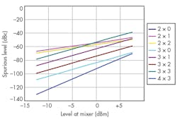
The spurious performance of a typical double-balanced mixer is shown in Fig. 2. It can be seen that it is critical to control the gain in front of the mixer and even modest levels of highpass filtering can greatly improve the performance.
Minimum Filtering Converter Architecture
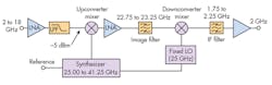
The minimum filtering topology shown in Fig. 3 uses a wideband tunable LO synthesizer. This allows the 2-to-18-GHz band to be upconverted in 500-MHz segments within a fixed 22.75-to-23.25-GHz frequency range. It is then downconverted using a fixed second LO to fall within the 1.75-to-2.25-GHz band that can then be readily processed.
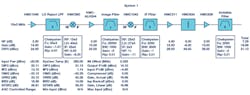
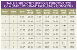
This frequency-conversion scheme takes maximum advantage of a single bandpass filter for all image filtering. Along with the fact that all RF × nLO spurious products (where n is the harmonic number) are above band, this provides excellent performance with almost no filtering. Table 1 shows predicted spurious performance at expected maximum input power levels.
For this example (Fig. 3), assuming a noise figure of 8 dB, bandwidth of 20 MHz, and 10-dB SNR, the instantaneous spurious-free dynamic range (SFDR) is greater than 55 dB, the upper limit of the SFDR is about -20 dBm, and the compression level is about 15 dB above the upper limit of the SFDR. For this architecture, the use of signal processing to minimize spurious levels can improve the total usable range of the system. In addition, all spurious signals not related to the input level are well out of band in this configuration. This architecture supports light-weight, miniature, and low-cost designs, but will be sensitive to high level interference and jamming as a result of the lack of preselection filtering.
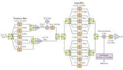
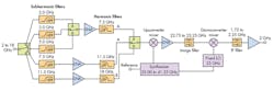
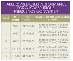
The architecture in Fig. 3 can be further improved in terms of spurious reduction by simple filtering (Fig. 4). This involves the addition of five highpass filters and three lowpass filters prior to upconversion. In this configuration, the 2-to-18-GHz band is upconverted in three bands: 2.0 to 7.5, 7.5 to 11.5, and 11.5 to 18.0 GHz.
This configuration offers ultimate spurious rejection of more than 20 to 30 dB by means of low-loss highpass and lowpass filters. The only exception is the image band, which is handled differently and only once. The only remaining significant spurious signals are harmonics of the RF input signal generated in components preceding the highpass filters.
The spurious levels for this architecture are summarized in Table 2. Ignoring the 2 × 0 and 3 × 0 spurious responses results in about 80-dB instantaneous SFDR. Using an image-reject mixer (IRM) for downconversion eases the millimeter-wave filter requirements and allow as much as 80-dB image rejection (the image being the largest spurious signal) with standard microstrip construction methods.
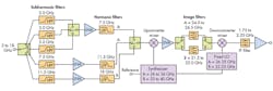
Further performance improvements can be obtained if additional filtering is added between the upconverted signal and prior to the second downconversion. Adding additional switch-filter components allows virtually all single-tone spurious signals to be eliminated (Fig. 5). The main result is to eliminate the 2RF direct harmonic feedthrough by using two selectable IF bands, as shown in Table 3.
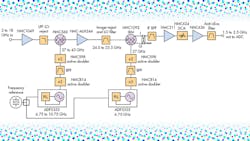
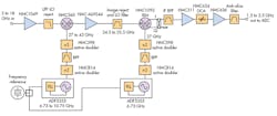
Numerous components employed in these frequency conversion architectures—such as amplifiers, mixers, attenuators, switches, frequency multipliers, frequency dividers, phase-locked loops (PLLs), and voltage-controlled oscillators (VCOs)—are available as integrated circuits (ICs) to shrink and simplify a frequency converter design. Figure 6 offers an example of a frequency converter design using components from Analog Devices.4
In this example, input RF signals are upconverted in the first conversion stage and then downconverted in the second conversion stage; this shifts higher-order spurious products out of the passband. These components are available as packaged devices for surface-mount application on PCBs.
Between the two mixers, the only critical filter is the bandpass filter. The lowpass filter at the input serves to minimize LO leakage through the input port. The bandpass filter after the second mixer minimizes in-band second harmonics caused by the IF amplifiers and falling within band of the anti-alias filter and also provides additional LO rejection. There are many ways to create the LOs for this signal chain depending on system requirements. The example of Fig. 6 presents a simple, high-performance method for generating the LO with newly available PLL/VCO ICs from Analog Devices, with the performance shown in Fig. 7.
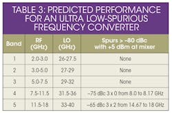
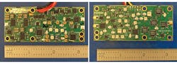
Figure 8 shows an example of a wideband multichannel receiver designed with several catalog components surface mounted on a multilayer circuit board. The board is populated with parts both on the front and back sides and is very compact, measuring 3.25 × 1.5 × 0.060 in. Passive components, ground connections, and signal interconnections are contained within various circuit-board layers.
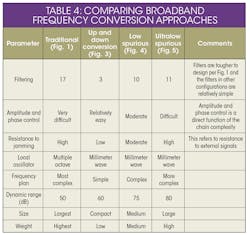
Selection of any broadband frequency converter topology is dependent on several performance metrics. Table 4 offers a comparison of various types of frequency converters and their respective merits. System-level decisions will depend upon such factors as size, weight, and power consumption as well as cost and time to market.
Digital approaches to wideband frequency conversion have not been included in this comparison but are described in ref. 3. Whether traditional analog frequency techniques or direct-digital conversion techniques are considered, the selection criteria apply when it comes to frequency planning, spurious mitigation, and noise considerations. The main change in a digital approach is to replace the second downconversion stage in an analog architecture with a high-speed analog-to-digital converter (ADC) and perform signal processing in the first and second Nyquist zones.
The development of broadband frequency converters is greatly simplified by the availability of many of the required components as standard ICs, including amplifiers, mixers, VCOs, frequency dividers/multipliers, and PLLs.4 The use of these components makes possible affordable, high-performance wideband frequency converters.
Gerald Cornwell, Senior Business Development Manager for Modules and Subsystems
Chandra Gupta, Director of Business Development for Modules, Systems and Space Products
Analog Devices, Inc., One Technology Way, P.O. Box 9106, Norwood, MA 02062; (781) 329-4700, (800) 262-5643
References
1. M. Edwards, “Leveraging the Use of a Radio Frequency Planning (RFP) Design Tool for Modern System Design,” High Frequency Electronics, December 2013.
2. "A Graphical Approach to Mixer Spurious Analysis," RF Cafe.
3. "High Performance Programmable Direct Conversion Receiver Platform," Microwave Journal, November, 2011.
4. RF and Microwave ICs Selection Guide 2015, Analog Devices.
Looking for parts? Go to SourceESB.
This file type includes high resolution graphics and schematics when applicable.
