Phased-Array Antennas Aid Wireless Communications
This file type includes high resolution graphics and schematics.
Wireless systems overcome a number of different limitations to provide reliable coverage, including limited available frequency bandwidth and efficient use of the available bandwidth. This efficiency can be boosted by using higher modulation rates, more sensitive receivers, and more accurate bit error detection/correction methods. Nevertheless, wireless telecommunication systems must still comply with the bandwidth or spectrum limitations established by governing authorities. And once bandwidth is used in one area, the bandwidth is not available for other systems, resulting in a limitation in data speeds.
1. A typical cellular communications site used three different frequency channels.
Because of this, current wireless communications technologies are limited in terms of data and user capacities. For example, a typical GSM cell site divides 360 deg. of coverage into three sectors with three frequency channels (Fig. 1). Within a sparsely populated area this may be acceptable; however, networks covering dense urban areas often require hundreds of such cell sites. Such a large number of sites incur high costs associated with the cell equipment, site management, and site rental. In addition, with every new site, RF planning becomes more complex. These same difficulties and high costs impact all wireless communications systems, including third-generation (3G) cellular, Long Term Evolution (LTE), and WiMAX systems. In a 3G system, if each of three or six sectors employs the same band (Fig. 2), the system will suffer a reduction of codes per sector due to interference between sectors. Wireless systems in densely populated areas can also suffer from signal cancellations due to multiple reflections (known also as multipath), as well as from losses due to absorption from building materials, precipitation, and vegetation.
2. A typical 3G cell site repeats the same frequency in three channels.
Related Articles
• Helical Antenna Links GSM/UMTS
• Phased-Array Antennas Aid Wireless Communications
• Compact Automotive Antennas Juggle Multiple Bands
Fortunately, wireless non-interfering multiple-output (NIMO) systems can overcome the bandwidth and capacity limitations in densely populated areas. These systems combine beamforming techniques with multiple-input, multiple-output (MIMO) architectures to provide higher quality of service (QoS) than systems based on conventional beamforming methods. NIMO strategies can provide multiple narrow beams from a single antenna, enabling improved efficiency, user capacity, and throughput.
The two types of MIMO currently employed in wireless systems are MIMO Matrix A and MIMO Matrix B. Both use more than one antenna to minimize signal fading. The antennas can be placed within a single mechanical structure or exist as separate mechanical structures. Radios that transmit and receive signals in these wireless systems can typically select between MIMO Matrix A and MIMO Matrix B depending on conditions along communication links. MIMO Matrix A uses two or more distinct paths with the same information transmitted to a subscriber and back (Fig. 3). If fading or multipath affects one path, at least one other path is available as a backup. A receiver will be designed to distinguish or combine the two (or more) signal paths as needed to overcome the fading or multipath effects. In a MIMO Matrix B approach, two (or more) distinct signal paths carry different signals over the same frequency band (Fig. 4). In this method, twice as much data can be transmitted, increasing the efficiency of the link. The signals are received at different times or with sufficiently different directions of arrival to differentiate them, with the assumption that fading will not be so severe that at least one path has enough energy to maintain the communications link.
This file type includes high resolution graphics and schematics.
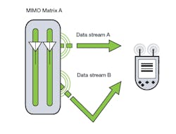
3. In the MIMO Matrix A approach, both data streams are the same.
Beamforming techniques create a narrow beam from a high-gain, phased-array antenna to link a subscriber and base station. Of the two types of beamformers, one uses software to mathematically construct the beam and the second, NIMO, employs hardware for the same effects. Through beamforming, communications systems can surpass the capabilities of MIMO techniques for increased system coverage and capacity.
Beamforming can generally increase the power of a signal in the direction in which it is transmitted. For reception, it can increase receiver sensitivity in the direction of desired signals and decrease sensitivity in the direction of interference and noise. In these ways, beamforming can provide longer communications distances and wider coverage areas. With NIMO, a greater number of subscribers can be reached with higher data rates. NIMO combines beamforming approaches with beam-shaping techniques to reduce sidelobe levels for higher transmission efficiencies.
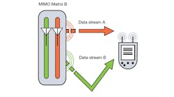
4. In the MIMO Matrix B approach, data stream A carries different data than data stream B.
Processing requirements for software-based beamforming can be quite sophisticated and resource-intensive, depending on the complexity of the channel (environment) and the number of subscribers connected on the system. Implementation of software-based beamforming approaches can result in delays of 5 to 10 ms, which can limit the number of subscribers who are connected. Such delays are not an issue with NIMO systems.
Narrow beams can be generated from high-gain phased-array antennas by using advanced signal-processing techniques. Narrow beams offer numerous advantages in wireless communications systems, including high antenna gain; longer communications distances; wider coverage areas; reduced multipath; lower interference (from the narrower beams); the capability of using adaptive phased-array-antenna schemes; and low sidelobe interference. Disadvantages of software-based narrow beams include the time delays needed to switch beams from customer to customer (50 to 10 ms); reduced number of customers served because of signal-processing delays; and no significant increase in data rates per customer.
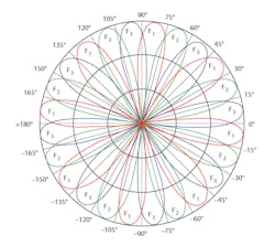
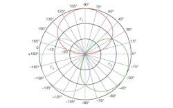
5. This is a graphic depiction of a NIMO system with 24 beams and 3 frequency channels: F1, F2, and F3.
NIMO is a novel approach toward a phased array antenna and beamforming system that can be used to overcome bandwidth and capacity limitations on dense wireless networks. It is a hardware-based fully passive beamforming system, combining beamforming technology with MIMO and beam shaping techniques and supporting transparent integration with any telecommunication system. NIMO provides multiple simultaneous narrow beams (Fig. 5) using a single phased array antenna and provides improved characteristics compared to conventional beamforming techniques. As many as 48 beams may be employed in a 360-deg. angle; however, for mobile systems as many as 12 beams is recommended. NIMO’s multibeam phased array antenna system increases spectral efficiency and throughput.
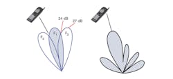
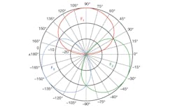
6. This is a graphical representation of a NIMO system with two channels: F1 and F2.
Compared to tradition MIMO systems, NIMO methods offer numerous advantages, including high antenna gain; long communication distances; wide coverage areas; reduced multipath effects; low interference because of the narrow beams; the opportunity to use a large number of beams (as many as 12 beams per 90-deg. antenna or as many as four beams per 120-deg. antenna for mobile systems); high data rates due to frequency reuse; minimal sidelobes due to beamshaping; a large number of customers that can be served, owing to multiple beams and frequency reuse; robustness and reliability, since NIMO is a passive system approach; and reduction in implementation costs compared to other approaches. The main disadvantage of NIMO is the lack of an adaptive phased-array antenna scheme, since it is not needed to minimize sidelobe levels (Fig. 6).
To overcome the limitations of modern wireless communication systems, equipment manufacturers have devised various equipment improvements ranging from increased modulation rates, MIMO, software beamforming, and NIMO. Phased-array antenna subsystems are employed for some of these techniques. While increasing the modulation rate can increase data speeds per customer, there are limits to the distances over which higher modulation rates can be used.5 Fortunately, hardware-based NIMO techniques can provide significant advantages compared to software-based beamforming approaches, when needs exist for improved wireless system performance and increased coverage especially in densely populated areas.
References
1. Electromagnetic Technologies Industries, Inc., white paper, “Simply Years Ahead,” 2009, www.etiworld.com.
2. Motorola, white paper, “A Practical Guide to WiMAX Antennas: MIMO and Beamforming Technical Overview,” Motorola, Libertyville, IL, www.motorola.com.
3. Electromagnetic Technologies Industries, Inc., white paper, “ETI Multibeam/Bandwidth for Free,” 2010, www.etiworld.com.
4. Constantine A. Balanis, Antenna Theory, 3rd Ed., Wiley, New York, 2005.
5. Terry Norman, “WiMAX vendor consolidation continues as Cisco withdraws from the market, Analysis Mason, March 2010, www.analysysmason.com.
This file type includes high resolution graphics and schematics.
