This file type includes high resolution graphics and schematics when applicable.
Multicarrier communications systems have become commonplace, squeezing more and more signals into increasingly limited frequency bands. Having transmitters and receivers loosely spaced in frequency is never easy, especially when intermodulation distortion from one more or transmitters can cause interference that degrades the performance of a receiver. Signals sharing the same transmission path can mix together, causing intermodulation not only in active devices and components, but in passive components as well.
Passive intermodulation (PIM) can originate from almost any passive component, including antennas, cables, connectors, and power dividers. Knowing how and why it starts can help to stop it, or at least minimize PIM to acceptable levels below a receiver’s sensitivity.
PIM is caused by the nonlinear behavior of different materials and how they are assembled to form passive components. Levels of distortion become more significant at higher power levels because of their increased current densities. Components with high ferromagnetic material content (such as iron, nickel, and steel) are particularly susceptible to PIM, exhibiting nonlinear voltage/current relationships.
That being said, even low-PIM materials are subject to PIM; this can occur whenever the RF/microwave transmission path through them is not clean and clear. Any poor mechanical junction in a transmission path, such as gaps in conductors or loose connectors, can cause PIM. In addition, surface defects on transmission paths, like rust or oxidation, can also be a starting point for PIM.
PIM is a concern when it falls within the frequency range of a receiver with sufficient sensitivity to detect it. As newer wireless carriers attempt to provide more customers with more service over limited bandwidths, they employ base stations in which transmitters and receivers are diplexed, or where two or more transmit frequencies may share the same antenna. Both cases are invitations to PIM, especially for poorly fitted or matched components and dirty or corroded transmission paths (e.g., poor connections to the antenna).
At higher power levels, such as those used by cellular base station transmitters, PIM can reach levels that that are above the sensitivity of a nearby receiver—a cellular handset, for instance—and can block the reception of desired signals carrying voice, data, or video information. Fourth-Generation (4G) cellular communications networks using frequency-division-duplex (FDD) techniques require high levels of signal fidelity and can suffer performance degradation, with loss of audio quality on cell phones and diminishing of data rates as a result of excessive levels of PIM.
Carrier signals and their harmonics mix to generate PIM generation, with distortion levels diminishing as the order of the mixing products increases. While third-, fifth-, and seventh-order intermodulation products from a given transmitter may fall in the operating frequency range of a nearby receiver, usually the third- and fifth-order products are the only ones at power levels sufficient to exceed the sensitivity of a receiver.
Of course, with the growing number of wireless devices and frequency bands commonly in use, PIM from the transmitter(s) of one wireless application may also fall within the receive range of another wireless application. Hence, it can be useful to at least know where several orders of where PIM products may fall, so as to determine whether they can cause interference for other wireless receivers in range.
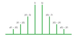
The two main intermodulation products of concern are third- and fifth-order intermodulation, which for two frequencies (f1 and f2) are produced by the mixing of fundamentals and harmonics (Fig.1):
Third-order intermodulation: 2f1 – f2
Fifth-order intermodulation: 3f1 – 2f2
These mixing products are concern when they fall within a receiver’s passband. For example, for a transmitter broadcasting tones at 870 and 890 MHz, the third-order intermodulation is 2(870) – 890 = 850 MHz, while the fifth-order intermodulation is 3(870) – 2(890) = 830 MHz. Intermodulation is also produced by the sum of the carriers and different harmonics, but this distortion will occur at much higher frequencies—usually out of the range of an applicable receiver.
While using components designed for low-PIM performance is advisable in systems with receivers and transmitters closely spaced in frequency, PIM is not always predictable; its behavior can change over time and operating conditions, such as temperature. Low PIM levels may be validated when commissioning a cell site or base station, but those levels can worsen over time as mechanical junctions in the transmission path deteriorate. Keeping any transmission junctions free of dirt, rust, oxidation, or corrosion is essential to maintaining low long-term PIM performance, and testing for PIM can confirm that suitable performance levels are being maintained.
Even printed-circuit boards (PCBs) are subject to PIM, such as in printed antennas for wireless communications devices and systems, depending upon their composition and the types and layouts of transmission lines fabricated on them. Various PCB material manufacturers offer low-PIM grades of their materials, fabricated with materials less likely to give rise to PIM at higher power levels.
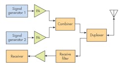
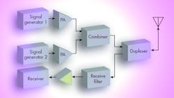
Measuring PIM levels has grown easier in recent years due to the growing number of portable battery-powered high-frequency spectrum analyzers that can be used for on-site testing, as well as several dedicated PIM testers from various suppliers. When testing is performed with a spectrum analyzer—rather than an all-in-one tester—two signal generators or an arbitrary waveform generator capable of providing two independent test signals will be needed to simulate two signals giving rise to intermodulation products. In addition, a pair of amplifiers will likely be needed to boost the test signals to levels comparable to those produced within the transmitter’s transmission path.
PIM levels are usually gauged by means of reflective testing. For example, two signals are injected into a device under test (DUT) or into a transmission path, such as leading to an antenna, and the levels of PIM are analyzed from the reflected signals at the input port of the DUT or transmission path (Fig. 2). Cables are usually part of the test setup, but they can also be part of the PIM problem. Coaxial cables may be the source of PIM in a high-frequency transmitter, but they may also be used to test for PIM in from the same transmitter.
Such cables should be manufactured with the appropriate materials and properly tested for low-PIM performance, lest they contribute to the signals under test. A number of suppliers offer low-PIM cables for such test purposes, with some also providing free-of-charge application notes on their use of their cables for PIM measurements.
The electrical length of a test cable can also affect the accuracy of a reflective PIM test, especially when the test is conducted with two fixed-frequency carriers (f1 and f2). Changing the frequencies of the two carriers and repeating the measurements can provide insight into the amount of signal addition and/or cancellation that might be taking place in the test cables to degrade the accuracy of the PIM measurements, and resulting in erroneous detected PIM levels.
For best results in a communications or test system, cable connectors should be connected with torque values as recommended by the cable assembly’s manufacturer. This will ensure a reliable transmission path without loose fittings and air gaps that can cause arcing at higher power levels, resulting in high PIM levels. When cleaning connector interfaces, whether for testing or maintaining communications systems performance, isopropyl alcohol has long been shown to be a reliable cleaning agent.
When evaluating components for PIM performance, make sure that fair comparisons are being made. Different datasheets present PIM in units of dBc or dBm. It is typically easier to compare the levels for different components using dBm, which is relative to the power level at 1 mW (0 dBm) compared to dBc, which is in turn relative to the carrier level. The use of dBc is fine when different components are characterized in similar ways, but difficult if comparing components that were tested for PIM at different carrier levels.
Looking for parts? Go to SourceESB.
This file type includes high resolution graphics and schematics when applicable.
About the Author
Jack Browne
Technical Contributor
Jack Browne, Technical Contributor, has worked in technical publishing for over 30 years. He managed the content and production of three technical journals while at the American Institute of Physics, including Medical Physics and the Journal of Vacuum Science & Technology. He has been a Publisher and Editor for Penton Media, started the firm’s Wireless Symposium & Exhibition trade show in 1993, and currently serves as Technical Contributor for that company's Microwaves & RF magazine. Browne, who holds a BS in Mathematics from City College of New York and BA degrees in English and Philosophy from Fordham University, is a member of the IEEE.
