Power Monitor Keeps Tabs on LMR System Performance
This file type includes high resolution graphics and schematics when applicable.
Challenges often rear up when trying to maintain the long-term reliability of commercial, industrial, and government land-mobile-radio (LMR) wireless-communications systems. Most of these systems must endure hostile environmental conditions, wear, rough handling, and even tampering. Many system owners continue to operate their systems without a reliable way to remotely monitor the performance levels of the many components comprising the system, including radios, power combiners, transmission lines, and antennas.
Fortunately, though, a solution exists in the form of the Channel Power Monitor from Bird Technologies. It’s designed to evaluate and monitor LMR systems operating from 144 to 960 MHz by checking the key elements of the transmission path in real time and alerting users of degraded performance or failures. The Channel Power Monitor tracks LMR system and component performance metrics over time, observing gradual performance degradation.
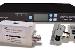
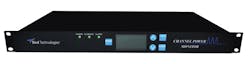
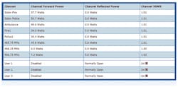
The model 3141 Channel Power Monitor Display (Fig. 1) occupies a single (1U) rack-mount space and can be set up and monitored either through a control panel on the front of the unit or via an Internet connection and a network-accessible webpage. Each website configured with a Channel Power Monitor has its own webpage to display performance measurements (Fig. 2), including forward and reflected power and voltage-standing-wave ratio (VSWR) at each key point in the LMR system.
The 3141 physically hosts the webpages. They provide integral Internet access, allowing for setup and configuration of the alarm functions with simple-network-management-protocol (SNMP) messaging capability that sends alerts via e-mail or as a text message to a mobile communications device.
Since reliability depends on so many factors, it’s impossible to know with absolute certainty that a radio or one of its components will fail. However, in many cases, total failure is preceded by a reduction in RF output power or an increase in VSWR. These situations can be difficult to spot, especially if a problem is intermittent, without the capability to view radio performance over time. The Channel Power Monitor addresses this issue by logging time-stamped data for as long as eight weeks for each sensor, which can be offloaded as a .csv file for analysis in Excel software from Microsoft Corp.
The Channel Power Monitor Display operates with a set of Bird’s directional and non-directional RF power sensors to form a system that can accommodate as many as 15 radio channels. It’s expandable to any size through the addition of expansion units and sensors that interface with the Channel Power Monitor Display. To simplify wiring in these kinds of setups, the 3141 uses a simple control line via an RJ-25 connector.
A typical system is designed so that power sensors are placed between each radio and the final system power combiner (Fig. 3). The power sensors help measure power through the LMR system’s component radios and transmission lines, as well as after the final system power combiner, where measurements can be made on forward and reflected power and LMR antenna VSWR. With such sensor positioning, it’s possible to spot degradation or failure at specific points in the system rather than only after the combiner (which would indicate only a problem with the system as a whole).
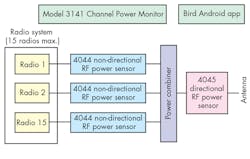
The Channel Power Monitor takes advantage of two sensors in particular. The model 4044 power sensor from Bird Technologies measures RF power to 100 W and, in the LMR communications-systems measurement setup, operates between the radio and combiner. Bird’s model 4045 power sensor handles measurements for power levels as high as 500 W. It’s placed after the output of the system combiner to read final system output-power levels.
This power-sensor-based measurement approach helps boost reliability when measuring and monitoring LMR communications systems. Some radio monitoring instruments rely on a scanning receiver to sweep over a broad frequency range, which offers the advantage of making frequency-specific measurements—but at 20% accuracy (approx.). As a result, the instrument would trigger an alert only after, say, a significant reduction in LMR-system RF output power that could dramatically reduce system performance.
In contrast, the power sensors in the Channel Power Monitor offer power-measurement accuracy of 5%. These power sensors are traceable to the National Institute of Standards and Technology (NIST), which provides much finer-grained measurements for earlier problem detection.
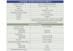
The 3141 includes a push-to-talk input for each radio in an LMR system. The measurement instrument features efficient operation, with power consumption of only 10 W from a 120/240-V ac power supply. It’s fully functional over a wide operating temperature range of 0 to +50°C (95% humidity, non-condensing) and delivers accurate measurements at altitudes as high as 10,000 ft. The table reveals more detailed specifications for the monitor instrument and the sensors.
For LMR system operators working at frequencies to 960 MHz, the Channel Power Monitor Display—when equipped with the appropriate power sensors—can provide a safety net for maintaining system performance at the levels expected by them and by their customers. P&A: $1800 (model 3141 Channel Power Monitor Display), $195 (model 4044 power sensor), and $550 (model 4045 power sensor); stock.
William Bates, Product Manager
Bird Technologies, 30303 Aurora Rd., Solon, OH 44139, (866) 695-4569
This file type includes high resolution graphics and schematics when applicable.
